


Return to Section TOC Return to Section TOC Return to Section TOC Return to Section TOC
Return to Master TOC Return to Master TOC Return to Master TOC Return to Master TOC
E-2
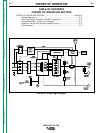
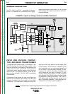
THEORY OF OPERATION
E-2
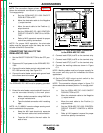
INPUT LINE VOLTAGE, CONTAC-
TOR, AND MAIN TRANSFORMER
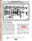
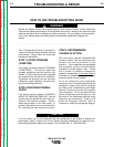
The desired three phase power is connected to the
DC-1000 through an Input Contactor located in the
input box at the rear of the machine. Two phases of the
input lines are also connected to the Control
Transformer which supplies power to the Contactor
Hold-In Circuit. The Contactor Hold-In Circuit will dis-
able the Input Contactor if the DC-1000 is overloaded
or overheated.
A Reconnect Panel allows the user to configure the
machine for the desired input voltage. This AC input
voltage is applied to the primary of the Main
Transformer. The transformer changes the high volt-
age, low current input power to a low voltage, high
current output. The finishes or “neutrals” of the
main secondary coils are connected together and
the six starts of the secondary windings are con-
nected to the rectifier assembly. In addition, the
main transformer also has an isolated 115 VAC
auxiliary winding that supplies 115 VAC to operate
the cooling fan and offers 8 amps of auxiliary power
to operate wire feeding equipment. The three 75
VAC phase angle windings are also housed in the
Main Transformer assembly. These windings pro-
vide power and “timing” to the Firing Board.
FIGURE E.2 - Input Line Voltage, Contactor and Main Transformer
IDEALARC DC-1000
NOTE: Unshaded areas of block logic diagrams are the subject of discussion.
GENERAL DESCRIPTION
The DC 1000 is an SCR - controlled DC power
source. It is designed to be controlled with a single
range potentiometer ouptut control. It can be used
for submerged arc or open arc automatic and semi-
automatic welding.