


Return to Section TOC Return to Section TOC Return to Section TOC Return to Section TOC
Return to Master TOC Return to Master TOC Return to Master TOC Return to Master TOC
F-60
TROUBLESHOOTING & REPAIR
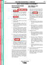
MAIN TRANSFORMER
DISASSEMBLY
1. Perform
Lift Bail Removal
Procedure
.
2. Remove lead #271 from resistor R3
(located near the input contactor).
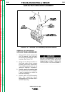
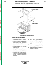
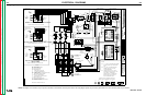
3. Separate the in-line connectors
from leads #211 and #212. See
Figure F.21.
4. Remove lead #256 from the choke
thermostat.
5. Remove lead #220 from the reed
switch (3CR).
6. Cut any necessary cable ties or
restraints and clear the leads nec-
essary for the removal of the top
transformer iron.
7. Using a 3/8” socket wrench, remove
two screws mounting the input con-
tactor bracket to the case back
assembly. With leads attached,
carefully pull assembly up and out
of the way. Set assembly aside.
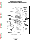
8. Using a 1/2” socket wrench, move
16 screws (8 on each side) from the
transformer side brackets. Taking
note of placement, remove the four
brackets and two bottom spacers.
See Figure F.26.
9. Using a 3/4” wrench, remove the six
nuts and lock washers from the
transformer threaded rods. It may
be necessary to hold the threaded
rods to keep them from turning.
10. Using a hoist, carefully lift the top
iron from the assembly. Note the
placement of shims and insulators.
NOTE: Some prying and jolting may be
necessary to free the iron from the coils.
Replace any coils that may be faulty. If
any heavy aluminum secondary coils
are to be replaced, identify and label all
leads to the transformer. The leads will
have to be cut and then TIG welded
upon reassembly.
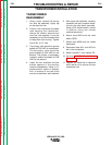
COIL REMOVAL AND
REPLACEMENT
1 Label and disconnect leads to the
coils that are being removed or
replaced (see Wiring Diagram).
2 Refer to Figure F.26 for proper coil
locations (top, bottom, left, right,
and center) of primary and sec-
ondary coils. If secondary coils are
to be replaced, it will be necessary
to cut the leads and TIG weld upon
reassembly.
3. Remove the coils:
a. Some prying and jolting may be
necessary to free the coils from
the iron.
b. Note placement of insulation
and wedges for reassembly
(especially primary coil to lami-
nation insulation and secondary
to primary insulation).
4. Replace the coils:
a. Be sure to replace all insulation
and wedges that were removed
(lamination to coils, and primary
to secondary coils).
b. Using a high temperature
industrial epoxy, such as
Lincoln E1603, glue the coils in
place by applying the epoxy to
the coil sides along the lamina-
tion, cell insulation, and
wedges.
c. Glue the secondary coils in
place from the iron to the coil
sides.
5. Re-TIG weld the secondary coil
leads (if previously cut).
6. When reconnecting any aluminum
leads, apply a thin layer of Dow
Corning 340 Heat Sink Compound
to mating surfaces.
IDEALARC DC-1000
MAIN TRANSFORMER DISASSEMBLY
F-60