


C-2
ACCESSORIES
C-2
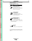
OPTIONS/ACCESSORIES
• Remote Control Box Assembly (K775)
• LN-7
• LN-8
}
Semi-Automatic Wire Feeders
• LN-9
• NA-3
• NA-5
}
Automatic Wire Feeders
• LT-7 and LT-56 Tractors
METERS
Optional factory-installed voltmeter and ammeter are
available.
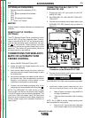
REMOTE OUTPUT CONTROL -
(OPTIONAL)
The K775 Remote Output Control consists of a control
box with 28 ft. (8.4 m) four conductor cable. This con-
nects to terminals #75, #76, #77 on the terminal strip,
and the case grounding screw marked with the sym-
bol on the machine. These terminals are made
available by opening the terminal access cover on the
case front. This control will give the same control as
the output control on the machine.
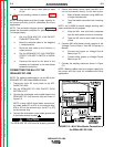
CONNECTIONS FOR SEMI-AUTO-
MATIC OR AUTOMATIC WIRE
FEEDER CONTROL
1. Set the ON/OFF PUSH BUTTON to OFF.
2. Locate and open the hinged access door on the
Front Case Assembly.
3. Insert control cable through the strain relief box
connector and pull enough cable through to reach
the terminal strip.
4. Connect the automatic wire feeder control cable to
the terminal strip. See corresponding connection
diagram in this section of the manual, or the
instructions included with the wire feeder.
5. Connect the wire feeder grounding wire to the
chassis ground screw marked with the symbol .
NOTE: The IDEALARC DC-1000 Auxiliary Power
Circuit (at #31 and #32 on the terminal strip) supplies
115-volt AC power to the wire feeding equipment. The
circuit has a 1000 volt ampere rating. An 8-amp slow
blow fuse on the machine’s control panel protects the
auxiliary power supply from excessive overloads or
short circuits.
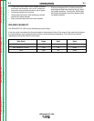
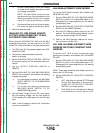
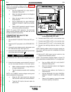
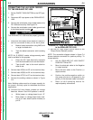
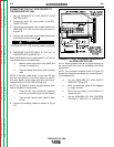
CONNECTING THE NA-3 OR LT-7 TO
IDEALARC DC-1000
1. Disconnect main AC input power to the IDE-
ALARC DC-1000.
2. Set IDEALARC DC-1000 ON/OFF PUSH BUT-
TON to OFF.
3. Connect the wire feeder control cable leads to the
IDEALARC DC-1000 terminal strip as shown in
Figure C.1.
4. Connect the wire feeder control cable ground lead
to the frame terminal marked .
5. Extend wire feeder control cable lead #21 so it
can be connected directly to the work piece.
a. Make a bolted connection using AWG #14
or larger insulated wire.
b. Tape the bolted connection with insulating
tape.
NOTE: An S-16586-X remote voltage sensing work
lead is available for this purpose.
c. Keep the #21 lead electrically separate
from the work cable circuit and connection.
IDEALARC DC-1000
Return to Section TOC Return to Section TOC Return to Section TOC Return to Section TOC
Return to Master TOC Return to Master TOC Return to Master TOC Return to Master TOC
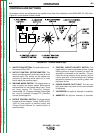
FIGURE C.1 - NA-3 or LT-7 Wire Feeder
Connection to the IDEALARC DC-1000
CAUTION
The IDEALARC DC-1000 must be properly grounded.
____________________________________________________