


Return to Section TOC Return to Section TOC Return to Section TOC Return to Section TOC
Return to Master TOC Return to Master TOC Return to Master TOC Return to Master TOC
A-7
INSTALLATION
IDEALARC DC-1000
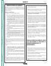
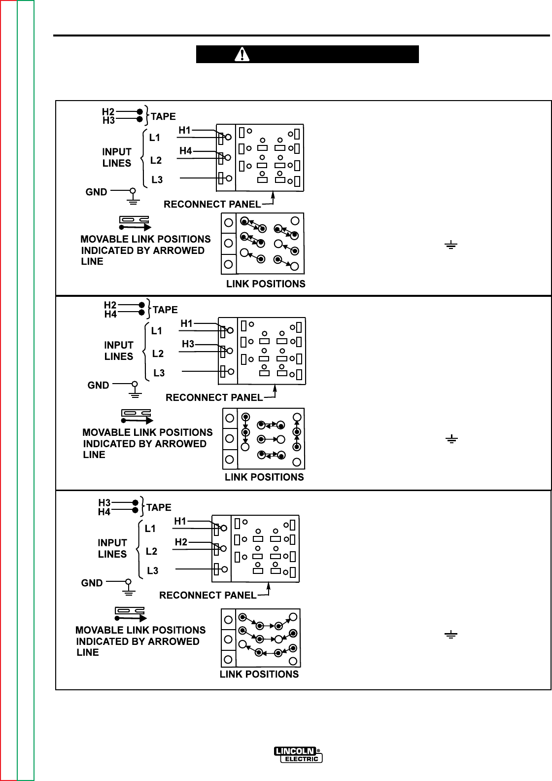
All input power must be electrically disconnected before touching panel.
____________________________________________________
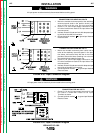
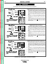
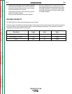
CONNECTION FOR 440 VOLTS 50 Hz (460V, 60 Hz.)
1. On reconnect panel, loosen all hex bolts, pull back
movable links, and rotate links to their new positions.
Position each link between the wire terminal and hex
bolt, push the link completely forward, and securely
tighten all hex bolts. Do not remove hex bolts at any
time.
2. Connect L1, L2, and L3 input supply lines and H1
and H4 control transformer leads to input terminals
as shown.
3. Insulate unused H2 and H3 lead terminal with ade-
quate tape to provide at least 600 volt insulation.
4. Connect terminal marked to ground per National
Electrical Code.
CONNECTION FOR 380 VOLTS 50 Hz.
1. On reconnect panel, loosen all hex bolts, pull back
movable links, and rotate links to their new positions.
Position each link between the wire terminal and hex
bolt, push the link completely forward, and securely
tighten all hex bolts. Do not remove hex bolts at any
time.
2. Connect L1, L2, and L3 input supply lines and H1
and H3 control transformer leads to input terminals
as shown.
3. Insulate unused H2 and H4 lead terminal with ade-
quate tape to provide at least 600 volt insulation.
4. Connect terminal marked to ground per National
Electrical Code.
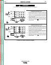
CONNECTION FOR 220 VOLTS 50 Hz. (230V 60 Hz.)
1. On reconnect panel, loosen all hex bolts, pull back
movable links, and rotate links to their new positions.
Position each link between the wire terminal and hex
bolt, push the link completely forward, and securely
tighten all hex bolts. Do not remove hex bolts at any
time.
2. Connect L1, L2, and L3 input supply lines and H1
and H2 control transformer leads to input terminals
as shown.
3. Insulate unused H3 and H4 lead terminal with ade-
quate tape to provide at least 600 volt insulation.
4. Connect terminal marked to ground per National
Electrical Code.
FIGURE A.3d - Input Supply Connection Diagram
WARNING
A-7