


Return to Section TOC Return to Section TOC Return to Section TOC Return to Section TOC
Return to Master TOC Return to Master TOC Return to Master TOC Return to Master TOC
F-47
TROUBLESHOOTING & REPAIR
F-47
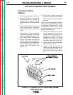
DO NOT APPLY INPUT POWER TO
THE DC-1000 WITH
THE CONTACTOR
COVER PLATE
REMOVED. POWER
APPLIED WITHOUT
COVER PLATE IN
POSITION MAY CAUSE SEVERE
ARCING RESULTING IN BODILY
INJURY.
________________________________________
3. Blow out any dirt or dust from in
and around contacts.
4. Examine contacts for signs of wear.
5. If contacts are stuck together or
overheated, parts of the contactor,
or the entire assembly, should be
replaced.
CONTACTOR REPLACEMENT
REMOVAL
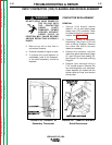
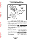
1. Using a 11/16” wrench, remove
leads L1, L2, L3 and output power
leads from 1CR contactor. Mark
and label all leads for proper recon-
nection. See Figure F.19.
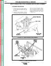
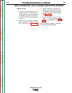
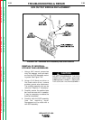
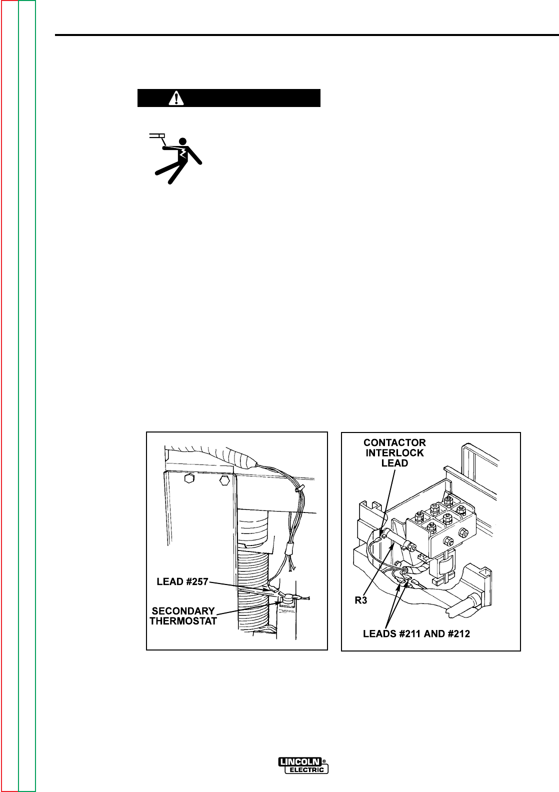
2. Remove lead #257 at secondary
thermostat. See Figure F.20 and
refer to Wiring Diagram. Remove
any cable ties and/or harness
looms as necessary.
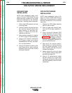
3. Remove the contactor interlock
leads from quick disconnects (leads
211 and 212) and from resistor R3.
See Figure F-21 and refer to Wiring
Diagram.
4. Remove input contactor using a
7/16” socket wrench. Remove the
four mounting bolts, nuts, and asso-
ciated washers (or loosen the two
bottom bolts and nuts, and remove
the top two).
IDEALARC DC-1000
INPUT CONTACTOR (1CR) CLEANING AND/OR REPLACEMENT
WARNING
FIGURE F.20 - Lead #257 at
Secondary Thermostat
FIGURE F.21 - Lead #211 and #212
Quick Disconnects