


F-28
TROUBLESHOOTING & REPAIR
F-28
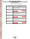
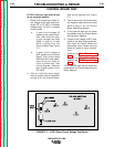
IF LED 2 does not light when #2 and
#4 are jumpered together.
1. Check for the presence of open cir-
cuit voltage at the weld output ter-
minals (27 to 75 VDC in constant
voltage mode, 75 VDC in constant
current mode).
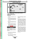
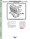
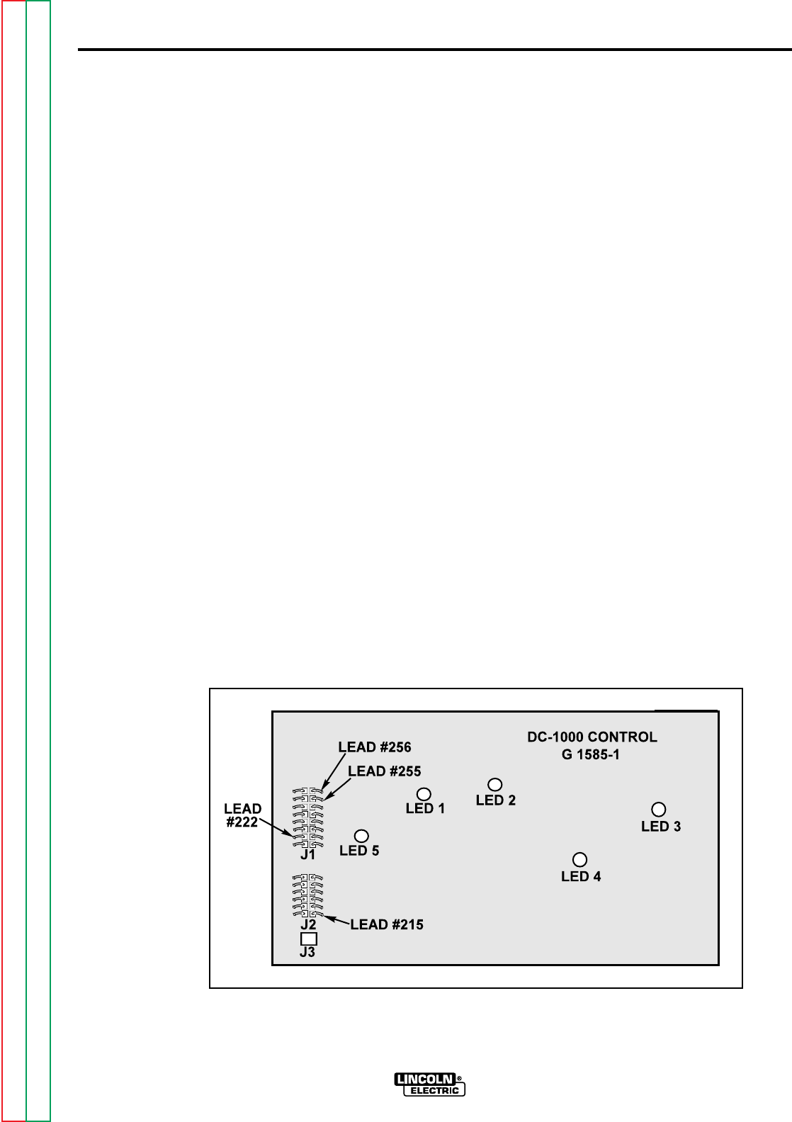
a. If open circuit voltage IS
present at the output termi-
nals, then check for open
circuit voltage from lead
#222 (-) plug J1 to lead
#215 (+) plug J2 on the
Control Board See Figure
F.11.
b. If open circuit voltage is
NOT present at the Control
Board, then check leads
#222 and #215 and associ-
ated wiring for loose or
faulty connections. See
wiring diagram. Remove
main supply power to the
DC-1000.
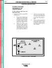
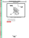
2. Test for continuity (zero ohms)
from the output shunt to lead #215
at plug J2 on the Control Board.
See wiring diagram and Figure
F.11.
3. Test for continuity (zero ohms) from
the negative output terminal to lead
#222 at plug J1 on the Control
Board. See wiring diagram.
4. If the previous tests do not reveal
the problem then the Control Board
may be faulty. Replace.
5. If open circuit voltage is NOT mea-
sured at the weld output terminals,
then check the Output Choke and
associated heavy current carrying
leads for loose or faulty connec-
tions.
• Perform the
Main Transformer
Test
.
• Perform the
Firing Board Test
.
• Perform the
SCR Output Bridge
Test
.
If the previous tests do not reveal the
problem then the Control Board may be
faulty. Replace.
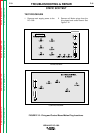
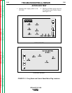
CONTROL BOARD TEST
IDEALARC DC-1000
Return to Section TOC Return to Section TOC Return to Section TOC Return to Section TOC
Return to Master TOC Return to Master TOC Return to Master TOC Return to Master TOC
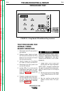
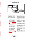
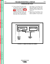
FIGURE F.11 - LED 2 Open Circuit Voltage Test Points