


F-29
TROUBLESHOOTING & REPAIR
F-29
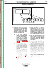
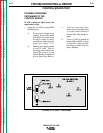
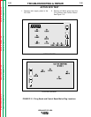
IF LED 3 does not light when the
Start Button is depressed (but LED 1
does light).
The Fault Protection Relay (2CR) is not
receiving supply voltage (24 VDC) and
the Input Contactor (1CR) will not stay
closed. Check to see if LED 4 lights or
“flickers” when the Start Button is held
in.
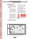
If LED 4 lights,
1. There may be a “short” at the
welder output terminals or the
remote control circuit (leads #73,
#74, # 75, #76 and #77) may be
shorted to the negative welding
voltage. Check the weld output ter-
minals and associated leads and
also the remote control circuitry.
See wiring diagram.
2. If the above procedures do not
reveal the problem, then the
Control board may be faulty-
Replace.
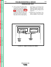
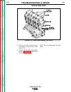
IF LED 5 does not light and varies in
brightness when #2 and #4 are
jumpered together, while the Output
Control Potentiometer is rotated .
The Control Board may be faulty-
Replace.
NOTE: The Weld Mode Switch (SW4)
must be in the CV position and the
Output Control Switch (SW3) in the
“Output Control at DC-1000” position.
Also check the Output Control
Potentiometer and associated circuitry.
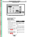
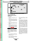
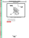
CONTROL BOARD TEST
IDEALARC DC-1000
Return to Section TOC Return to Section TOC Return to Section TOC Return to Section TOC
Return to Master TOC Return to Master TOC Return to Master TOC Return to Master TOC