


F-37
TROUBLESHOOTING & REPAIR
F-37
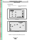
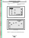
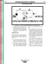
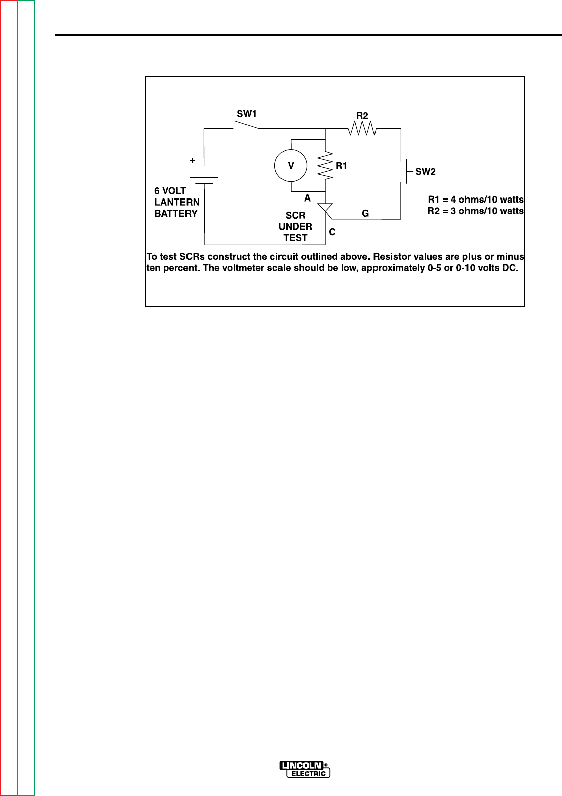
5. To test SCRs, construct the circuit
outlined in Figure F.17. Use one 6V
lantern battery. Resistor values are
in ohms ±10%. The voltmeter scale
should be low, approximately 0-5 or
0-10 volts.
BATTERY TEST
Check the battery by shorting leads (A)
and (C) and then close switch SW1.
Replace battery if voltage is less than
4.5 volts.
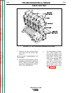
A. Connect SCR into the test circuit as
shown (A) lead to anode (C) lead to
cathode and (G) lead to the gate.
B. Close switch SW1 (switch SW2
should open), voltmeter should read
zero. If the voltmeter reads higher
than zero the SCR is shorted.
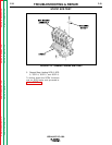
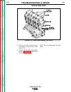
NOTE: Do not disassemble the heat
sinks.
6. With switch SW1 closed, close
switch SW2 for two seconds and
release. The voltmeter should read
3 to 6 volts before and after switch
SW2 is released. If the voltmeter
does not read, or reads only while
SW2 is depressed, the SCR or bat-
tery is defective (repeat Battery
Test Procedure).
7. Open switch SW1, disconnect the
gate lead (G) and reverse the (A)
and (C) leads on the SCR. Close
switch SW2. The voltmeter should
read zero. If the voltage is higher
than zero, the SCR is shorted.
8. Replace any SCR assembly that
does not pass test in Step 4.
ACTIVE SCR TEST
IDEALARC DC-1000
FIGURE F.17- Silicon Controlled Rectifier (SCR) Test Setup
Return to Section TOC Return to Section TOC Return to Section TOC Return to Section TOC
Return to Master TOC Return to Master TOC Return to Master TOC Return to Master TOC