


F-22
TROUBLESHOOTING & REPAIR
F-22
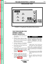
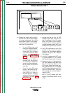
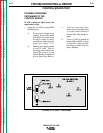
10. Rotate the output control poten-
tiometer (R1). As the potentiometer
is turned clockwise, the LEDs
should glow brighter. As the poten-
tiometer is turned counter-clock-
wise, the LEDs should dim.
a. If the LEDs glow and
change in brightness equal-
ly as the potentiometer is
turned and the problem
continues, then the SCR
bridge may be faulty.
Perform the
SCR Bridge
Test
.
b. If any or all of LEDs 1
through 6 do not glow, or
do not change in brightness
equally as the potentiome-
ter is turned, continue to
next step.
c. If one or two LEDs stay
bright or dim while the oth-
ers change, this could indi-
cate either an open or
shorted gate or a faulty
snubber on the related SCR
assembly. Perform
SCR
Bridge Test
.
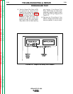
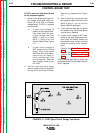
11. Locate and test for 6 to 15 VDC
between leads #231 and #215 on
the Firing Board in the CV mode.
When the output control poten-
tiometer (R1) is rotated, the DC
voltage between leads #231 and
#215 should vary from 6 to 15 VDC.
12. If an LED continues to be lit and
should not be, a circuit may be
faulty on the Firing Board between
a Molex plug and LED. Replace
Firing Board.
13. If the DC voltage does NOT vary,
as potentiometer (R1) is rotated,
the Control Board may be faulty.
14. Locate and test for approximately
5.8 VDC between leads #231 and
#215 on the Firing Board in VV
(CC) mode. When the output con-
trol potentiometer (R1) is rotated,
the DC voltage between leads #231
and #215 should NOT vary and
should remain at a constant approx-
imate 5.8 VDC.
NOTE: The DC voltage may vary
slightly at the lower portion of the
range.
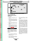
FIRING BOARD TEST
IDEALARC DC-1000
Return to Section TOC Return to Section TOC Return to Section TOC Return to Section TOC
Return to Master TOC Return to Master TOC Return to Master TOC Return to Master TOC
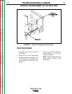
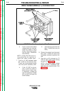
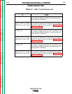
FIGURE F.7 - Terminal Strip Jumper Wire Connections