


F-43
TROUBLESHOOTING & REPAIR
F-43
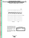
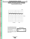
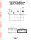
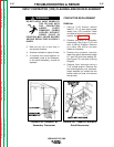
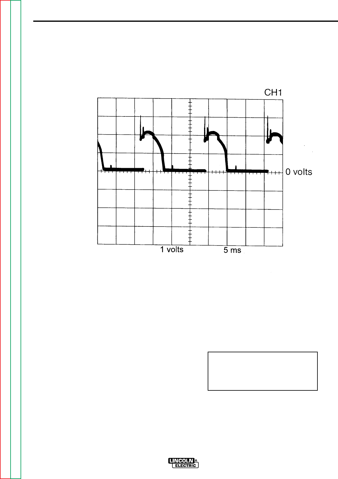
TYPICAL SCR GATE VOLTAGE WAVEFORM
CONSTANT VOLTAGE INNERSHIELD
MAXIMUM OUTPUT SETTING - NO LOAD
IDEALARC DC-1000
SCOPE SETTINGS
Volts/Div. . . . . . . . . . . . . . 1 V/Div.
Horizontal Sweep . . . . . .5 ms/Div.
Coupling . . . . . . . . . . . . . . . . . DC
Trigger . . . . . . . . . . . . . . . Internal
This is the typical SCR gate pulse volt-
age waveform. The machine was in an
open circuit condition (no load) and
operating properly. Note that each verti-
cal division represents 1 volt and that
each horizontal division represents 5
milliseconds in time.
Note: Scope probes connected at SCR
gate and cathode: (+) probe to gate, (-)
probe to cathode.
Return to Section TOC Return to Section TOC Return to Section TOC Return to Section TOC
Return to Master TOC Return to Master TOC Return to Master TOC Return to Master TOC