


F-14
TROUBLESHOOTING & REPAIR
F-14
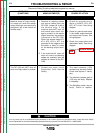
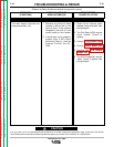
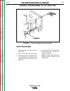
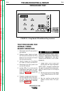
TEST PROCEDURE
1. Disconnect main AC input power to
the machine.
2. Remove the Top and Case Sides.
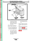
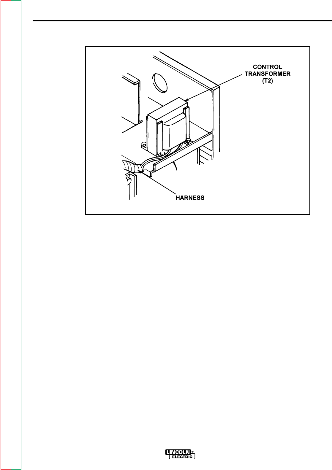
3. Locate the Control Transformer (T2)
on the left side of the Input Box (fac-
ing the back of the machine). See
Figure F.1.
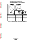
4. Locate the Control Transformer
primary leads (H1, H2, H3, etc.).
See wiring diagram.
NOTE: Unused leads should be
taped. Check for loose or faulty
connections.
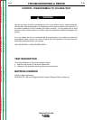
CONTROL TRANSFORMER (T2) VOLTAGE TEST
IDEALARC DC-1000
Return to Section TOC Return to Section TOC Return to Section TOC Return to Section TOC
Return to Master TOC Return to Master TOC Return to Master TOC Return to Master TOC
FIGURE F.1 - Control Transformer Lead Location