


F-27
TROUBLESHOOTING & REPAIR
F-27
POSSIBLE PROBLEMS
PERTAINING TO THE
CONTROL BOARD
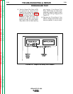
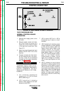
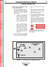
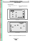
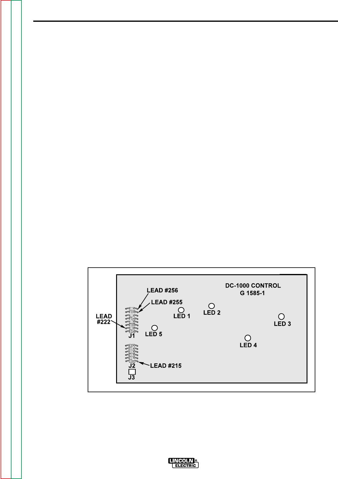
IF LED 1 does not light, when the
start switch is ON.
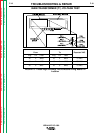
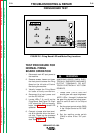
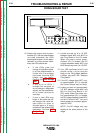
1. Check for 115 VAC at leads #255
to #256 plug J1
a. If the correct voltage is not
present, check leads #255
and #256 and associated
wiring for loose or faulty
connections. See wiring dia-
gram and Figure F.10.
b. Remove main supply power
to the DC-1000. Test for
continuity (zero ohms) from
lead #255 plug J1 at the
Control Board to lead #212
at the Start/Stop Button.
c. Test for continuity (zero
ohms) from lead #256 plug
J1 at the Control Board to
the pilot light. See wiring dia-
gram.
d. If the 115 VAC is present at
leads #255 to #256 at plug
J1 and LED 1 does not light,
the Control Board may be
faulty. Replace.
CONTROL BOARD TEST
IDEALARC DC-1000
Return to Section TOC Return to Section TOC Return to Section TOC Return to Section TOC
Return to Master TOC Return to Master TOC Return to Master TOC Return to Master TOC
FIGURE F.10 - LED 1 Test Points