


C-3
ACCESSORIES
C-3
d. Tape the #21 lead to work cable for ease
of use.
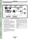
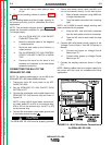
6. Connect the welding cables as shown in Figure
C.1.
NOTE: Welding cables must be of proper capacity for
the current and duty cycle for immediate and future
applications.
NOTE: The connection diagram shown in Figure C.1
shows the electrode connected for positive polarity.
To change polarity:
a. Set the IDEALARC DC-1000 ON/OFF
PUSH BUTTON to OFF.
b. Move the electrode cable to the Negative
(-) output terminal.
c. Move the work cable to the Positive (+)
output terminal.
d. Set the IDEALARC DC-1000 CONTROL
CIRCUIT POLARITY SWITCH to NEGA-
TIVE.
e. Reverse the leads at the back of the
ammeter and voltmeter on the wire feeder
automatic control box.
CONNECTING THE NA-5 TO THE
IDEALARC DC-1000
NOTE: For optimum performance, use the NA-5 with
IDEALARC DC-1000 codes
8288
and above.
1. Disconnect main AC input power to the IDE-
ALARC DC-1000.
2. Set the IDEALARC DC-1000 ON/OFF PUSH
BUTTON to OFF.
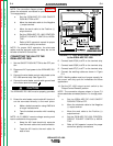
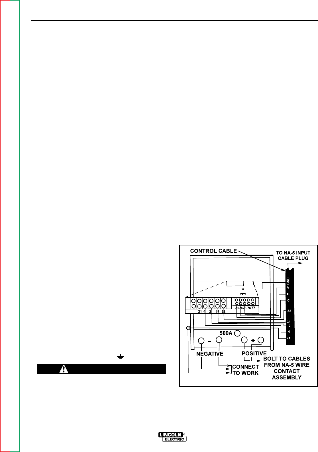
3. Connect the wire feeder control cable leads to the
IDEALARC DC-1000 terminal strip as shown in
Figure C.2.
NOTE: If using a K215 control cable, connect con-
trol cable leads #75 to #75 on the terminal strip,
#76 to #74 on the terminal strip, and #77 to #73
on the terminal strip.
4. Connect the wire feeder control cable ground lead
to the frame terminal marked .
5. Extend wire feeder control cable lead #21 so it
can be connected directly to the work piece.
a. Make a bolted connection using AWG #14
or larger insulated wire.
b. Tape the bolted connection with insulating
tape.
NOTE: An S-16586-X remote voltage sensing work
lead is available for this purpose.
c. Keep the #21 lead electrically separate
from the work cable circuit and connection.
d. Tape the #21 lead to work cable for ease
of use.
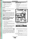
6. Connect NA-5 wire feeder control jumpers on the
Voltage Control Board. See NA-5 Operator’s
Manual.
a. Connect red jumper on Voltage Control
Board to pin “S.”
b. Connect white jumper on Voltage Control
Board to pin “B.”
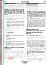
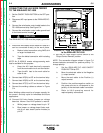
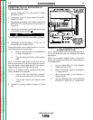
7. Connect the welding cables as shown in Figure
C.2.
NOTE: Welding cables must be of proper capacity for
the current and duty cycle for immediate and future
applications.
IDEALARC DC-1000
Return to Section TOC Return to Section TOC Return to Section TOC Return to Section TOC
Return to Master TOC Return to Master TOC Return to Master TOC Return to Master TOC
FIGURE C.2 - NA-5 Wire Feeder Connection to
the IDEALARC DC-1000
CAUTION
The IDEALARC DC-1000 must be properly grounded.
____________________________________________________