


Return to Section TOC Return to Section TOC Return to Section TOC Return to Section TOC
Return to Master TOC Return to Master TOC Return to Master TOC Return to Master TOC
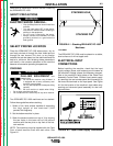
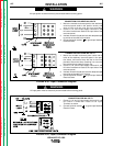
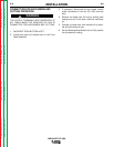
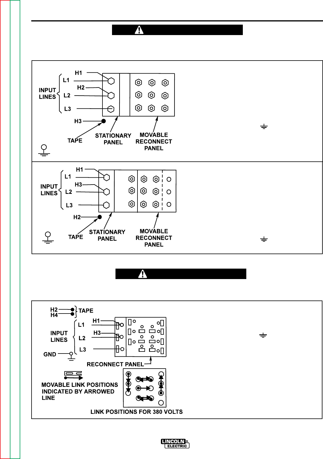
CONNECTION FOR UNDER 300 VOLTS
1. Mount the movable reconnect panel to the stationary
reconnect panel studs in the position shown, and
secure firmly with the nine hex nuts provided.
2. Conect L1, L2, and L3 input supply lines and H1 and
H2 control transformer leads to the input side of the
reconnect panel.
3. Insulate unused H3 lead terminal with adequate tape
to provide at least 600 volt insulation.
4. Connect terminal marked to ground per National
Electrical Code.
A-5
INSTALLATION
IDEALARC DC-1000
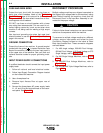
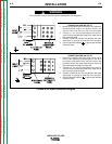
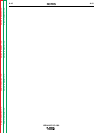
CONNECTION FOR OVER 300 VOLTS
1. Mount the movable reconnect panel center set of
holes to the stationary reconnect panel in the posi-
tion shown, and secure firmly with the six hex nuts
provided. Secure the three remaining hex nuts over
the remaining three studs for future use.
2. Conect L1, L2, and L3 input supply lines and H1 and
H3 control transformer leads to the input side of the
reconnect panel.
3. Insulate unused H2 lead terminal with adequate tape
to provide at least 600 volt insulation.
4. Connect terminal marked to ground per National
Electrical Code.
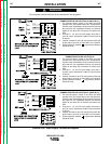
CONNECTION FOR 380 VOLTS
1. Conect L1, L2, and L3 input supply lines and H1 and
H3 Control Transformer Leads to the Input
Terminals as shown.
2. Connect terminal marked to ground per National
Electrical Code.
All input power must be electrically disconnected before touching panel.
____________________________________________________
All input power must be electrically disconnected before touching panel.
____________________________________________________
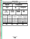
FIGURE A.3b - Input Connection Diagram
WARNING
WARNING
FIGURE A.3a - Input Connection Diagram
A-5