


F-21
TROUBLESHOOTING & REPAIR
F-21
TEST PROCEDURE FOR
NORMAL FIRING
BOARD OPERATION
1. Disconnect main AC input power to
the machine.
2. Remove screws, loosen and lower
the front panel to access the Firing
Board on the left side of Control
Box facing the machine.
3. Visually inspect the Firing Board
for loose or faulty connections.
4. Reconnect the input power and
turn the DC-1000 on.
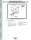
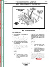
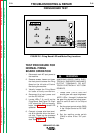
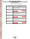
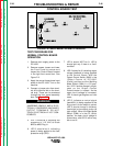
5. Locate LEDs 7, 8, and 9 on the
Firing Board. See Figure F.6. Each
LED should be ON and equally
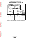
bright. Use Table F.1 to check LED
operation.
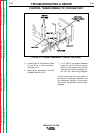
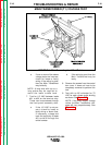
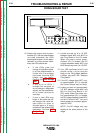
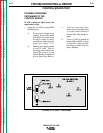
6. Connect a jumper wire from termi-
nal #2 to terminal #4 on the termi-
nal strip. These can be accessed
through the Front Panel Assembly
door. See Figure F.7.
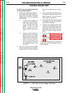
7. Locate LEDs 1 thru 6. Each LED
should glow with equal brightness.
NOTE: LEDs 1 through 6 indicate that
the gate firing signals are being gener-
ated to send to each of the output
SCRs.
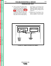
8. Set the output control switch (SW3)
in the “Output Control at DC-1000”
position.
9. Set the welding mode switch
(SW4) in either of the “CV” posi-
tions.
FIRING BOARD TEST
IDEALARC DC-1000
Return to Section TOC Return to Section TOC Return to Section TOC Return to Section TOC
Return to Master TOC Return to Master TOC Return to Master TOC Return to Master TOC
FIGURE F.6 - Firing Board LED and Molex Plug Locations
WARNING
JUMPERING LEADS 2 AND 4 ELEC-
TRICALLY ENERGIZES MACHINE’S
OUTPUT TERMINALS. DO NOT
TOUCH ELECTRICALLY HOT COM-
PONENTS.
______________________________________