


Return to Section TOC Return to Section TOC Return to Section TOC Return to Section TOC
Return to Master TOC Return to Master TOC Return to Master TOC Return to Master TOC
F-15
TROUBLESHOOTING & REPAIR
F-15
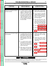
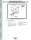
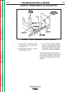
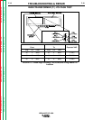
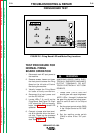
5. Locate Control Transformer leads
X1 and X2 at in line connectors.
See Figure F.2.
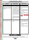
6. Apply power and test for 115 VAC
between leads X1 to X2.
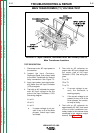
CONTROL TRANSFORMER (T2) VOLTAGE TEST
IDEALARC DC-1000
FIGURE F.2 - Control Transformer X1 and X2 Test Points
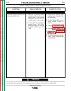
7. If 115 VAC is not present between
leads X1 and X2, test for correct
main AC input power to the Control
Transformer primary windings (H1,
H2, H3, etc.) See wiring diagram.
If the correct main AC input power to
the Control Transformer is present, and
the secondary voltage is not correct,
the Control Transformer may be faulty.
Replace.