


F-32
TROUBLESHOOTING & REPAIR
F-32
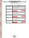
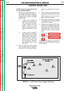
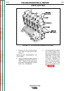
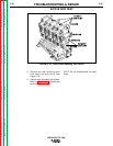
3. Remove the red insulating paint
from heat sink test points. See
Figure 13.
NOTE: DO NOT DISASSEMBLE THE
HEAT SINKS.
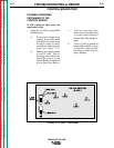
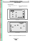
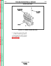
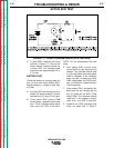
4. Using an analog ohmmeter, test the
resistance from anode to cathode of
SCR 1. Reverse the meter leads
and check from cathode to anode of
SCR 1. (R x 1000 SCALE)
a. If a low resistance is indicat-
ed in either direction, dis-
connect the snubber circuit
(See wiring diagram) and
retest SCR 1. If a low resis-
tance is still indicated, SCR
1 is faulty - Replace. If a
very high or infinite resis-
tance is indicated without
the snubber circuit, then
replace the snubber circuit,
See Figure F.14.
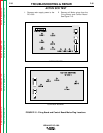
STATIC SCR TEST
IDEALARC DC-1000
Return to Section TOC Return to Section TOC Return to Section TOC Return to Section TOC
Return to Master TOC Return to Master TOC Return to Master TOC Return to Master TOC
FIGURE F.13 - SCR Heat Sink Assembly Test Points.