


Return to Section TOC Return to Section TOC Return to Section TOC Return to Section TOC
Return to Master TOC Return to Master TOC Return to Master TOC Return to Master TOC
THEORY OF OPERATION
E-3
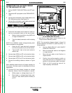
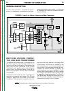
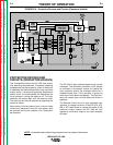
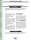
OUTPUT RECTIFICATION,
CONTROL, AND FEEDBACK
The neutrals of the Main Transformer secondary
windings are connected together and the six starts
are connected to the six SCR assemblies to form a
six phase output. This six phase AC output from the
Main Transformer secondary is rectified and con-
trolled through the SCR bridge. Output current is
sensed at the shunt, and output voltage is moni-
tored at the welding output terminals. This feedback
information is processed in the control board. The
control board compares the commands of the Mode
switch and the Output Control Potentiometer (or
Remote Control) with the feedback information and
sends the appropriate signal to the Firing Board.
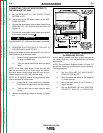
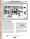
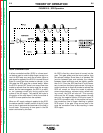
The Firing Board is a three phase circuit. Each
phase provides two firing pulses, one for each of
the two Silicon Controlled Rectifiers (SCR) con-
trolled by that phase. The firing circuit supplies the
proper amount of energy to the gates of the power
SCRs. When this gate signal is applied, at the cor-
rect time, the SCR will turn “ON”. The amount of
“ON” time versus “OFF” time determines the output
of the machine. See
SCR Operation
.
The Pilot Relay signals the Firing Board circuit to
supply gate pulses to the SCR Bridge. Closing of
the Pilot Relay (a “dry” closure of leads #2 and #4)
also brings the Latching Resistor into the machine
output circuit. The Latching Resistor provides a
pre-load for the SCR Bridge.
In later models (above code 9500) a Choke and
separate 500 amp output terminal is provided to
enhance lower current arc characteristics, espe-
cially for submerged arc and GMAW procedures
below 450 amps.
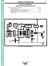
FIGURE E.3- Output, Rectification, Control and Feedback
IDEALARC DC-1000
NOTE: Unshaded areas of block logic diagrams are the subject of discussion.
E-3