


Return to Section TOC Return to Section TOC Return to Section TOC Return to Section TOC
Return to Master TOC Return to Master TOC Return to Master TOC Return to Master TOC
F-7
TROUBLESHOOTING & REPAIR
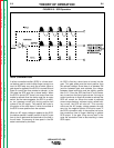
IDEALARC DC-1000
Observe all Safety Guidelines detailed throughout this manual
If for any reason you do not understand the test procedures or are unable to perform the tests/repairs safely, contact the Lincoln Electric
Service Department for technical troubleshooting assistance before you proceed. Call 216-383-2531 or 1-800-833-9353.
OUTPUT PROBLEMS
PROBLEMS
(SYMPTOMS)
POSSIBLE AREAS OF
MISADJUSTMENT(S)
RECOMMENDED
COURSE OF ACTION
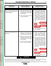
Machine has maximum weld out-
put and no control.
Machine has minimum output
and no control.
1. If remote control is being
used, put output control switch
(SW3) in “OUTPUT CON-
TROL AT DC-1000” position
and control weld output with
the output control (R1) at DC-
1000. If the problem is solved,
check the remote control unit
(or wire feeder) and associat-
ed control cable.
1. If a remote control unit is NOT
connected to the terminal strip
#73, #74,#75, #76, and/or #77
terminals, the output control
switch must be in the “OUT-
PUT CONTROL AT DC-1000”
position.
2. If a remote control cable is
connected to terminals #73,
#74, #75, #76, and/or #77, the
leads may be shorted to the
positive weld output.
3. Make certain the three phase
input voltage is correct and
matches the machine rating
and the reconnect panel.
1. Check output control switch
(SW3) and associated wiring.
2. Check feedback leads #222
(negative output terminal) and
#215, #210(output shunt) for
loose or faulty connections.
See wiring diagram.
3. Check the #75 lead for conti-
nuity (zero ohms) from the
output control potentiometer
(R1) to the control board plug
10J1. See wiring diagram.
4. Perform
Firing Board Test
.
5. Perform
Control Board Test
.
6. Perform
SCR Output Bridge
Test
.
1. Check the output control
potentiometer (R1) and asso-
ciated wiring.
2. Check the output control
switch (SW3) the welding
mode switch (SW4) and asso-
ciated wiring.
3. Perform the
Control Board
Test
.
4. Perform the
Firing Board
Test
.
5. Perform the
SCR Output
Bridge Test
..
6. Perform
Main Transformer
Test
.
CAUTION
F-7