


Rev. B
Workman 200 Spray SystemPage 3.1 -- 22Sonic Boom System (Optional Kit)
Service and Repairs
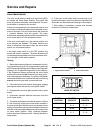
Sonic Mode Switch
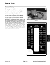
The sonic mode switch is used as an input for the ECU
to activate the Sonic Boom System. This switch has
three(3)positions: automatic,manual andoff.Thesonic
mode switch is located on the console.
If the sonic mode switch is in the automatic position, the
sonics ensors willbe activatedtoallow automaticmove-
ment of the boom. The tips of the booms will remain at
a constant distance from the ground. The boom
switchescanbeusedtoraise/lowerthebooms whenthe
sonic mode switch is in the automatic position.
If the sonic mode switch is in the manual position, the
sonic sensors are disabled. The boom switches are
used to raise/lower the booms when the sonic mode
switch is in the manual position.
If the sonic mode switch is in the OFF position, the
booms will remain in position. The boom actuators will
notbeenergized regardlessofsonicboom sensoractiv-
ity or change in boom switch position.
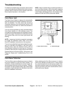
Testing
1. Before disconnectingthe sonic modeswitch for test-
ing, the switch and its circuit wiring should be tested as
aECU inputwiththe DiagnosticDisplay (seeDiagnostic
Display in the Tr oubleshooting section of this chapter).
If the Diagnostic Display verifies that the sonic mode
switchand circuitwiringarefunctioning correctly,nofur-
ther switchtesting is necessary.If, however, the Display
determines thatthe sonicmode switchand circuitwiring
are not functioning correctly, proceed with test.
2. Park vehicleon a level surface,stop engine, engage
parking brake and remove key from ignition switch.
3. Disassemble console to gain access to sonic mode
switch.
4. Disconnect harness electrical connector from the
sonic mode switch.
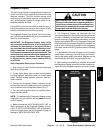
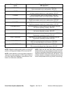
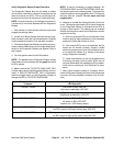
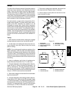
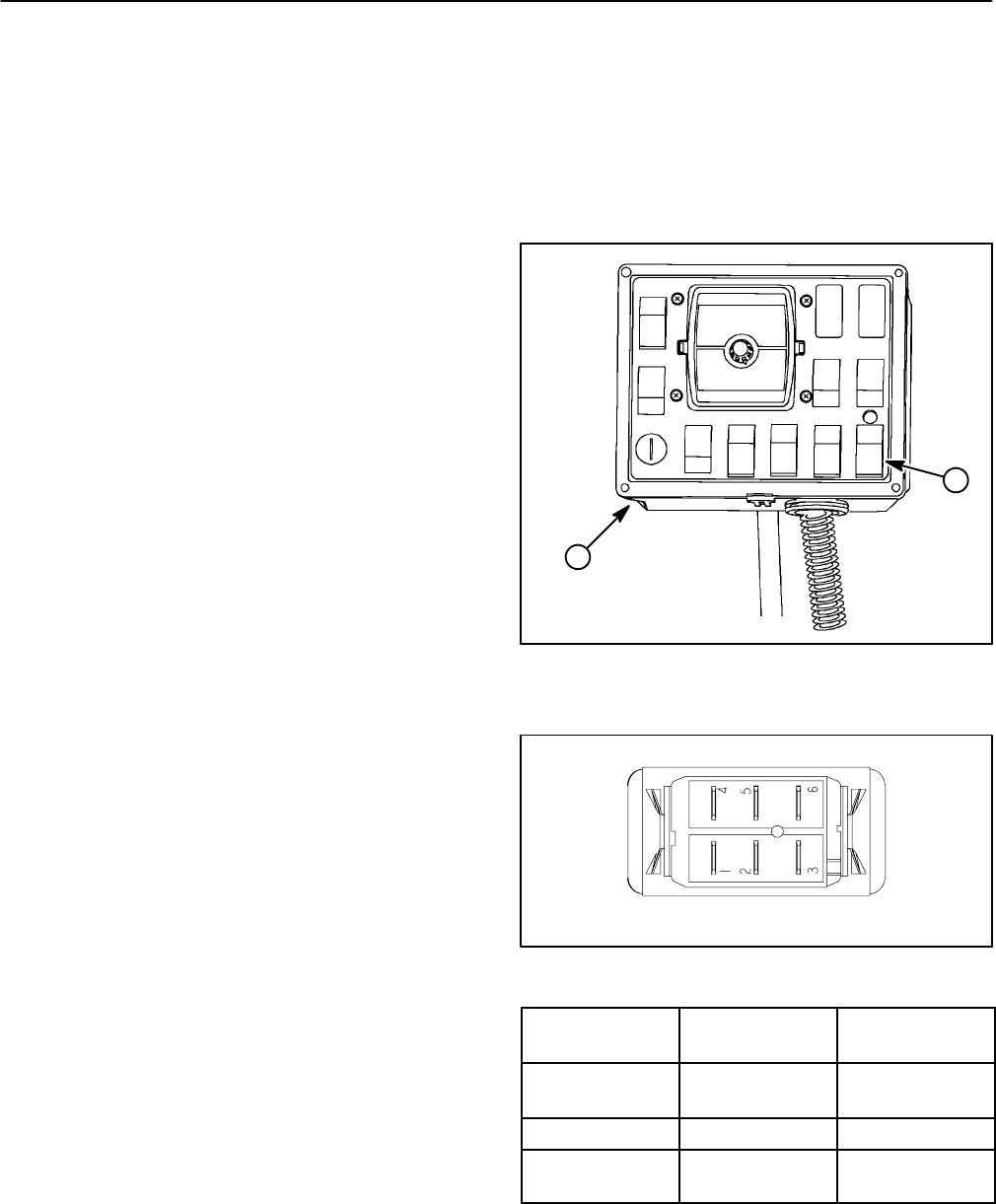
5. The switch terminals are marked as shownin Figure
9. The circuit logic of the sonic mode switch is shown in
the chartto the right.With theuse of a multimeter(ohms
setting),theswitchfunctionsmaybetestedtodetermine
whether continuity existsbetween the various terminals
for each switch position. Verify continuity between
switch terminals. Replace switch if testing identifies a
faulty switch.
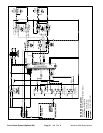
6. If the sonic mode switch tests correctly and circuit
problem still exists, check wire harness (see Electrical
Schematic and WireHarness Drawings in this chapter).
7. After testing is completed, connect wire harness
connector to the sonic mode switch.
1. Spray control console 2. Sonic mode switch
Figure 8
2
1
Figure 9
BACK OF SWITCH
SWITCH
POSITION
CLOSED
CIRCUITS
OPEN
CIRCUITS
AUTOMATIC 2+3
5+6
2+1
5+4
OFF NONE ALL
MANUAL 2+1
5+4
2+3
5+6