


Rev. B
Page 3 -- 27.1 Workman 200 Spray SystemSpray System
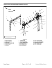
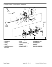
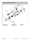
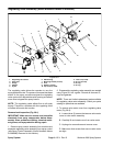
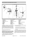
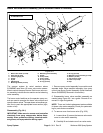
Regulating Valve Assembly (Serial Numbers Above 310000000)
Figure 28.1
2
3
6
8
9
10
11
13
1
5
7
12
14
4
10
7
11
9
12
1. Regulating valve motor
2. Hose barb
3. Flange
4. Adaptor
5. Flynut
6. Elbow fitting
7. Mounting bracket (2 used)
8. Fork
9. Washer (4 used)
10. Cap screw (4 used)
11. Lock nut (4 used)
12. O--ring (2 used)
13. O--ring
14. O--ring
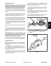
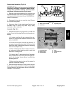
The regulating valve allows the operator to vary the
spray applicationrate. Thepressure increase/decrease
switch on the spray console energizes the regulating
valve motor which adjusts thevalve opening and allows
some flow to bypass the spray booms.
NOTE: The regulating valve affects flow to all spray
booms. Therefore, a problem with the regulating valve
will affect all booms and nozzles.
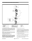
Removal and Inspection (Fig. 28.1)
IMPORTANT: Make sure to remove and neutralize
chemicals from spray components before disas-
sembly. Wear protective clothing, chemical resist-
ant gloves, and eye protection during repair.
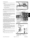
1. Remove spray control assembly from machine and
separate regulating valve assembly from spray control
(see Spray Control Assembly (Serial Numbers Above
310000000) Removal in this section).
2. Disassemble regulating valve assembly as needed
using Figure 28.1 as a guide. Discard all removed O--
rings and gaskets.
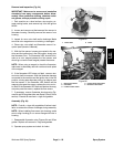
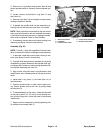
NOTE: There are limited replacement parts available
for regulating valve motor assembly. Check your parts
catalog for parts that are available.
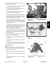
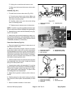
3. To remove valve motor cover from regulating valve
motor (Fig. 28.3):
A. Loosen three (3) screws that secure valve motor
cover to valve motor assembly.
B. Carefully lift and rotate cover from valve motor.
C. Unplug wire connections and remove cover.
D. Make sure that screws that secure valve motor
are tight.