


Workman 200 Ultra Sonic Boom System (Rev. C)Page 3.2 -- 17
Troubleshooting
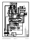
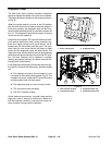
For effective troubleshooting and repairs, there must be
a good understanding of the electrical circuits and com-
ponents used on the Ultra Sonic Boom System (see Ul-
tra Sonic Boom System Operation in this chapter).
NOTE: When troubleshooting an electrical problem on
your Ultra Sonic Boom System, refer to information re-
garding the sonic boom light and diagnostic lamp in this
section. Also, use the Diagnostic Display (see Special
Tools in this chapter) to test Toro electronic controller
(TEC) inputs and outputs.
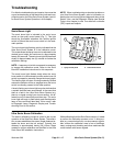
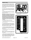
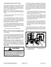
Sonic Boom Light
The sonic boom light is included in the sonic boom
switch on the spray control panel (Fig. 7). This light
should be illuminated whenever the vehicle ignition
switch is ON and the sonic boom switch is in the auto-
matic position.
The sonic boom light flashing quickly indicates that the
Ultra Sonic Boom System is in the calibration mode.
This modeallowsthe sprayboomsto beadjusted for the
desired boom height and continues for approximately
twenty(20) seconds.The sonic boomlight willthenflash
slowly for approximately two (2) minutes to finalize the
calibration settings.
NOTE: A sequence of switch movements is necessary
to engage t he calibration mode. Refer to the Sonic
Boom Kit Installation Instructions for this sequence.
The sonic boom light flashes slowly when the sonic
boom switch is in the automatic position a nd a boom l ift
switch is pressed to manually change the boom height.
The f lashing light will return to being constantly ON and
automatic operation will be re--engaged once the boom
switch is manually pressed to the lower position.
A slowly flashing sonicboom light mayalso indicatethat
a system fault has been encountered. In the event that
there is a fault in the Ultra Sonic Boom System (e.g.
there is no signal coming from a boom sensor), the af-
fected boom will raise b riefly and then stop. The sonic
boom light will begin to flash slowly and the diagnostic
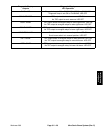
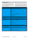
lamp on the console will also flash. If this occurs, refer
to Diagnostic Lamp, Diagnostic Display and Trouble-
shooting Chart in this section.
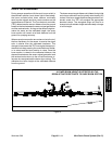
1. Spray control panel 2. Sonic boom switch
Figure 7
1
2
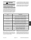
Ultra Sonic Boom Calibration
The sensor calibration process is critical to the correct
operation of the Ultra Sonic Boom System. The calibra-
tion process establishes the sensor target distance be-
tween the boom and the turf surface. Typically, this
distance is approximately twenty (20) inches. Steps
needed for proper calibration are identified in the Ultra
Sonic Boom Kit Installation Instructions.
Whilecalibrating theUltra SonicBoom sensors,itis best
to perform the calibration process on turf. A shiny sur-
face (e.g. cement shop floor) can skew sensor signals.
Also, ensure the calibration area is free of buildings,
trees, underground plumbing and other machines that
could interfere with sensor signals.
Ultra Sonic
Boom System