


Rev. B
Workman 200 Spray SystemPage 2 -- 8Electrical System
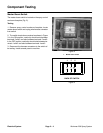
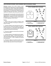
Hold and Boom Actuator (Serial Numbers Above 260000000) Relays
Workman sprayers w ith serial numbers below
260000000 use a s ingle relay for the sprayer hold func-
tion. Sprayers with serial numbers above 260000000
use the hold relay and four (4) additional relays for the
boom actuators.The hold and boomactuator relays are
locatedinthespraycontrolenclosure.Therelayscanbe
identified by a tag at the relay wire harness connector.
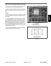
The relay used on sprayers with serial numbers below
260000000 (Fig. 11) has a different terminal layout than
relays used on sprayers with serial numbers above
260000000 (Fig.12). Relay operationand circuitlogic is
the same regardless of s erial number.
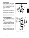
Testing
1. Remove spray c ontrol enclosure faceplate, locate
relay that is to be tested and unplug wire harness con-
nector from relay.
2. Connectmultimeter (ohmssetting) leadstorelay ter-
minals 30 and 87. Ground terminal 86 and apply + 12
VDC to terminal 85. The relay should make and break
continuity between terminals 30 and 87 as +12 VDC is
applied and removed from terminal 85.
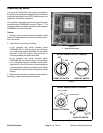
3. Disconnect voltage from terminal 85 and multimeter
lead from terminal 87.
4. Connectmultimeter (ohmssetting) leadstorelay ter-
minals 30 and 87A. Apply +12 VDC to terminal 85. The
relay should make and break continuity between termi-
nals 30 and 87A as +12 VDC is applied and removed
from terminal 85.
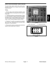
5. Disconnect voltage and multimeter leads from the
relay terminals. Reconnect relay to machine wire har-
ness and install spray control enclosure faceplate.
Figure 11
86
87A
30
87
85
86
85
87A 87
30
SERIAL NUMBER BELOW 260000000
2
1
3
4
1
1. Coil terminal
2. Common terminal
3. Normally closed term.
4. Normally open term.
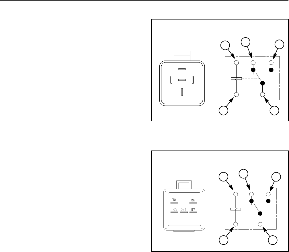
Figure 12
86
85
87A 87
30
2
1
3
4
1. Coil terminal
2. Common terminal
3. Normally closed term.
4. Normally open term.
1
SERIAL NUMBER ABOVE 260000000