


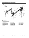
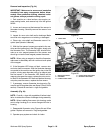
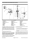

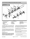
2. Remove four (4) phillips head screws (item 8) that
secure spindle section to housing. Remove spindle sec
-
tion.
3. Locate, remove, and discard o–ring (item 11) and
seal (item 14).
4. Remove valve (item 13) and inspect for wear and/or
damage. Replace if needed.
5. If needed, the spindle shaft can be removed by re-
moving lock nut that secures cone (item 12) to shaft.
NOTE: Many individual components for the rate control
motor and spindle section are not available separately.
If individual components are worn or damaged, assem
-
blies must be replaced. Refer to Parts Catalog.
6. If necessary, remove rate control valve housing from
machine (see Spray Control in this section).
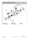
Assembly (Fig. 27)
NOTE: Coat all o–rings with vegetable oil before instal-
lation to reduce the chance of damage during assembly.
1. If removed, install rate control valve housing to ma-
chine (see Spray Control in this section).
2. If spindle shaft was removed, assemble by reversing
disassembly process. Make sure that spindle shaft sup
-
port aligns with notches in housing during assembly. Se-
cure spindle assembly with lock nut.
3. Align control valve with tabs in spindle section and
install control valve. Rotate spindle to fully retract control
valve.
4. Install new o–ring (item 11) and seal (item 14) to
spindle section.
5. Position spindle section to rate control valve hous-
ing. Secure spindle section with four (4) phillips head
screws (item 8).
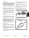
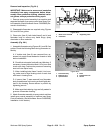
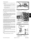
6. To ease assembly of the motor, rotate spindle shaft
so the post is about 1/2” (13 mm) from the spindle sec
-
tion housing. Align slot in motor with post in spindle and
install motor.
7. Secure motor to assembly by evenly tightening four
(4) phillips head screws (item 5).
1
2
5
3
4
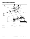
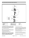
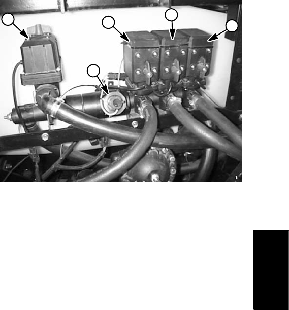
Figure 28
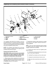
1. Rate control motor 4. Center boom valve motor
2. Flowmeter 5. RH boom valve motor
3. LH boom valve motor
Spray
System
Workman 200 Spray System
Page 3 – 27
Spray System