


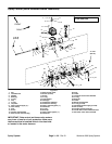
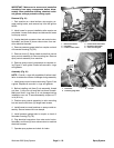
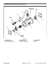
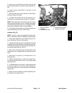
Removal and Inspection (Fig. 24)
IMPORTANT: Make sure to remove and neutralize
chemicals from spray components before disas
-
sembly. Wear protective clothing, chemical resist-
ant gloves, and eye protection during repair.
1. Park machine on a level surface, stop engine, en-
gage parking brake, and remove key from the ignition
switch.
2. Loosen and remove nut that secures flow sensor to
flowmeter housing. Carefully remove flow sensor from
housing.
1
2
3. Inspect for worn rotor shaft and/or bushings. Make
sure that rotor magnets are not missing or damaged.
4. Clean rotor, rotor shaft, and flowmeter sensor if re-
quired (see Operator’s Manual).
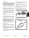
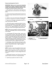
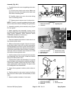
5. With the flow sensor harness connected to the ma-
chine and the ignition key in the ON position, slowly spin
the flowmeter rotor. The flowmeter LED should illumi
-
nate as a rotor magnet passes the flow sensor and
should go out as the next magnet passes the sensor.
NOTE: When using a magnet to check the flowmeter,
make sure to alternately use both north and south poles
of the magnet.
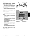
6. If the flowmeter LED does not flash, remove rotor
and rotor shaft from sensor. With the flowmeter harness
connected to the machine and the ignition key in the ON
position, slowly pass alternate poles of a magnet past
the flow sensor. If the flowmeter LED flashes as the
magnet poles pass the sensor, replace the rotor and ro
-
tor shaft. If the flowmeter LED does not flash as the mag-
net poles pass the sensor, replace the flow sensor.
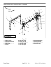
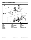
7. If necessary, remove flowmeter housing using Fig-
ures 24 and 26 as guides (also see Spray Control) in this
section). Discard all removed o–rings and gaskets.
Assembly (Fig. 24)
NOTE: Coat all o–rings with vegetable oil before instal-
lation to reduce the chance of damage during assembly.
NOTE: When installing flow sensor into housing, make
sure to align locating pin on sensor flange with hole in
housing.
1. Reassemble flowmeter using Figures 24 and 26 as
guides. Replace all removed o–rings and gaskets.
2. Operate spray system and check for leaks.
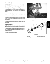
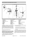
Figure 25
1. Rotor shaft 2. Rotor
1
2
5
3
4
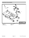
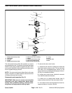
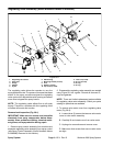
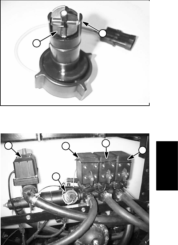
Figure 26
1. Rate control motor 4. Center boom valve motor
2. Flowmeter 5. RH boom valve motor
3. LH boom valve motor
Spray
System
Workman 200 Spray System
Page 3 – 25
Spray System