


Workman 200Ultra Sonic Boom System (Rev. C) Page 3.2 -- 26
Service and Repairs
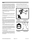
Sonic Boom Fuses
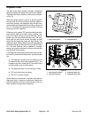
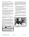
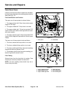
Fuses for the Ultra Sonic Boom system are included in
the fuseblocks attached tothe mounting plate underthe
dash panel (Fig. 13).
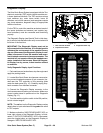
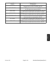
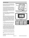
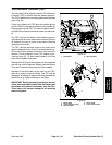
Fuse Identification and Function
The upper row of fuses protect circuits as follows:
1. The upper, extreme left 2 Amp fuse protects power
supply for TEC logic.
2. The upper, middle left 7.5 Amp fuse is not used.
3. The upper, middle right 7.5 Amp fuse protects TEC
output circuits (sonic boom switch light and boom actu-
ator power supply).
4. The upper, extreme right 7.5 Amp fuse protects TEC
output circuits (diagnostic light and sonic sensor power
supply).
The lower row of fuses protect circuits as follows:
1. The lower, extreme left fuse position is not used.
2. The lower, middle left fuse position is not used.
3. The lower, middle right 30 Amp fuse (auto resetting)
protects the left boom actuator circuit.
4. The extreme right 30 Amp fuse (auto resetting) pro-
tects the right boom actuator circuit.
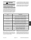
Fuse Testing
Remove fuses from the fuse block for testing. Fuse
should have continuity between fuse terminals.
NOTE: The auto resetting fuses should only be re-
moved if they are faulty.
1. Dash panel 2. Fuse blocks
Figure 13
1
2
1. Upper, extreme left fuse
2. Upper middle left fuse
3. Upper, middle right fuse
4. Upper right fuse
5. Auto resetting fuse
6. Auto resetting fuse
Figure 14
1
7
6
2
3
4
5