


Workman 200 Ultra Sonic Boom System (Rev. C)Page 3.2 -- 29
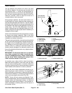
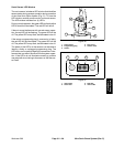
Sonic Sensor LED Window
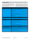
The sonic sensor includes a LED window that identifies
sensor status during sprayeroperation during operation
of the Ultra Sonic Boom system (Fig. 21). To view the
LED window, carefully remove cover from sonic sensor.
The LED window includes four (4) LED’s.
Duringnormaloperation,the greenLEDandboth yellow
LED’s should be illuminated. The red LED will be off .
If there is some interference with normal sensor opera-
tion, the red LED will be flashing. The green LED will be
off. Theyellow LED’s mayflash, be illuminated or be off.
If the sensor programming plug is removed or is faulty,
the red LED will be illuminated. The green LED will be
off. Theyellow LED’s mayflash, be illuminated or be off.
The status of the LED’s on t he sensors can be used to
identify a faulty or unplugged programming plug. The
LED’s also can be used to identify the presence of inter-
ference that can affect Ultra Sonic Boom system opera-
tion. If the LED’s do not illuminate correctly, a problem
mayexist withcircuit wiringtothe sensoror withthe sen-
sor itself.
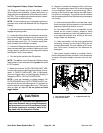
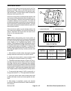
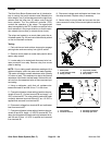
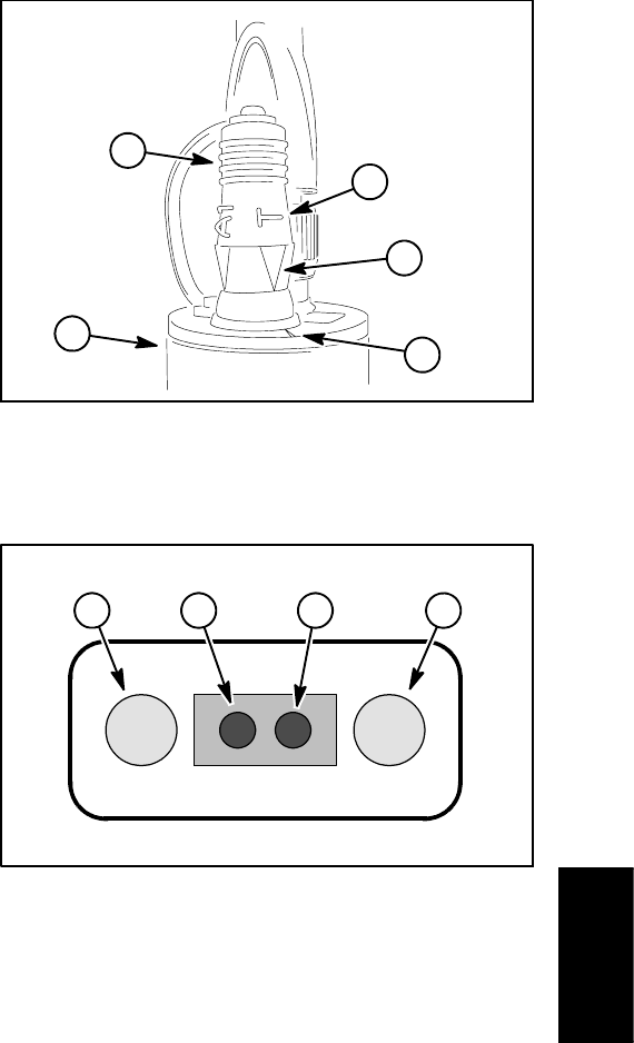
1. Sonic sensor
2. Programming plug
3. Letter T
4. Plug arrow
5. Sensor notch
Figure 20
2
3
4
1
5
1. Yellow LED
2. Green LED
3. Red LED
4. Yellow LED
Figure 21
2
4
1
3
Ultra Sonic
Boom System