


Rev. B
Workman 200 Spray System Page 2 -- 5 Electrical System
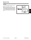
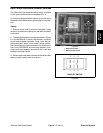
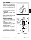
Rate Control and Boom Actuator Switches
The rate control (increase/decrease) switch is located
on the spray control enclosure faceplate (Fig. 4).
On machines equipped with the electric boom lift, this is
the sameswitch that isused to operatethe boom actua-
tors.
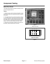
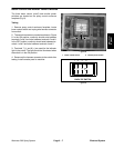
Testing
1. Remove spray c ontrol enclosure faceplate, locate
switch to be tested and unplug wire harness connector
from switch.
2. The switch terminals are marked asshown in Figure
5. In the INCREASE or boom raise position, continuity
should exist between terminals 2 and 3 and also be-
tween terminals 5 and 6. In the neutral, center position,
there should beno continuity between anyswitch termi-
nals. In the DECREASE or boom lower position, conti-
nuity should exist between terminals 2 and 1 and also
between terminals 5 and 4.
3. Reconnect the harness connector to the switchafter
testing. Install console panel to machine.
1. Rate control switch
2. Boom actuator switch
Figure 4
1
2
Figure 5
12
4
3
56
BACK OF SWITCH
Electrical
System