


Rev. A
Workman 200 Spray SystemPage 3 -- 4 4Spray System
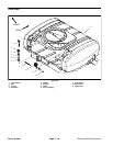
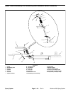
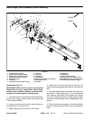
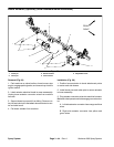
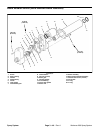
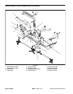
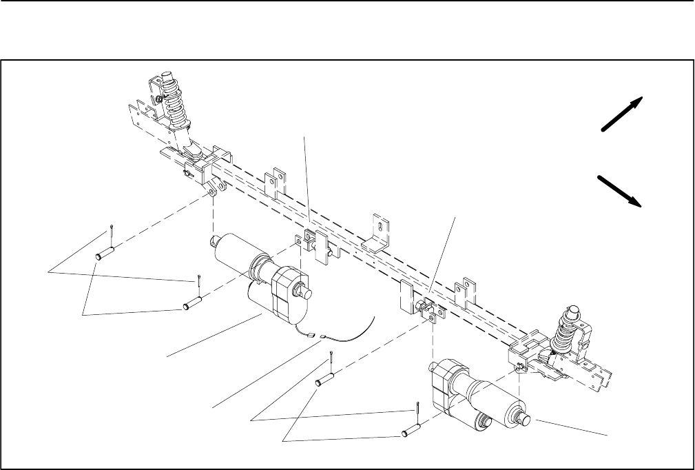
Boom Actuator (Optional) (Serial Numbers Below 260000000)
1. Cotter pin
2. Clevis pin
3. Boom actuator
4. Wire harness
5. Adjustable clevis
Figure 50
2
3
1
4
1
2
3
FRONT
RIGHT
5
5
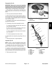
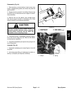
Removal (Fig. 50)
1. Park machine on a level surface, lower booms, stop
engine,engageparking brake,andremovekey fromthe
ignition switch.
2. Label actuator electrical leads to ease reassembly.
Unplug boom actuator connector wires from machine
harness.
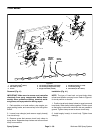
3. Support boomto prevent it fromfalling. Remove cot-
terpins andclevispins thatattachboomactuator tocen-
ter and side boom.
4. Pull boom actuator from machine.
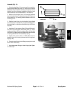
Installation (Fig. 50)
1. Position boom actuator to clevis attachment points
on center and side booms.
2. Install clevis pins and cotter pins to secure actuator
to boom assembly.
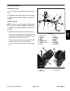
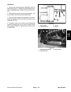
3. Plugactuatorconnectorwiresinto machineharness.
Makesure thatoperatorswitchesengagecorrect actua-
tor.
A. Leftside actuator connectorhas orangeand blue
wires.
B. Right side actuator connector has yellow and
green wires.