


Rev. B
Workman 200 Spray System Page 3.1 -- 23 Sonic Boom System (Optional Kit)
Relays
The Sonic Boom System uses six (6) identical relays to
control the boom actuators and ultimately the boom
height. Three (3) of the relays control the right actuator
and the other three (3) relays control the left actuator.
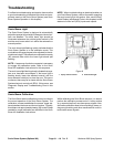
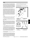
The electronic control unit (ECU) controls the operation
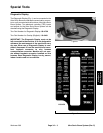
ofthe relays.The relaysare locatedon amounting plate
underthe vehicledashpanel (Fig.10) andcanbe identi-
fied by a label on the wire harness connector.
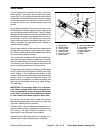
For each actuator, a power switch relay and two (2) H--
bridge relays are used. The power switch relay is ener-
gized by the ECU whenever the actuator is to be
energized to change boom height (either lowered or
raised).Both H--bridge relaysare energizedby theECU
when a boom is to be raised. The energized bridge re-
lays provide current flow to the actuator so the actuator
retracts. The H--bridge relays are not energized w hen a
boomistobelowered.Thenon--energizedbridgerelays
provide current flow to the actuator so the actuator ex-
tends.
Testing
1. Park vehicleon a level surface,stop engine, engage
parking brake and remove key from ignition switch.
2. Locate relay to be tested and disconnect wire har-
ness connector from relay. Remove relay from mount
plate for testing.
NOTE: Prior to taking small resistance readings with a
digital multimeter, short the meter test leads together.
The meter will display a small resistance value (usually
0.5 ohms or less). This resistance is due to the internal
resistance of the meterand test leads. Subtract this val-
ue from from the measured value of the component you
are testing.
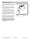
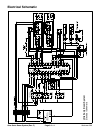
3. Using a multimeter, verify that coil resistance be-
tween terminals 85 and 86 is from 71 to 88 ohms.
4. Connectmultimeter (ohmssetting) leadstorelay ter-
minals 30 and 87. Ground terminal 86 and apply +12
VDC to terminal 85. The relay terminals 30 and 87
shouldhavecontinuity as+12VDCisappliedtoterminal
85.The relayterminals 30and 87should nothave conti-
nuity as +12 VDC is removed from terminal 85.
5. Disconnect voltage from terminal 85 and multimeter
lead from terminal 87.
6. Connectmultimeter (ohmssetting) leadstorelay ter-
minals 30 and 87A. With terminal 86 grounded, apply
+12 VDCto terminal 85.The relay terminals30 and87A
should not have continuity as +12 VDC is applied to ter-
minal 85. The relay terminals 30 and 87A should have
continuity as +12 VDC is removed from terminal 85.
7. Disconnect voltage and multimeter test leads from
the relay terminals. Replace relay if necessary.
8. Secure relay to mount plate and connect wire har-
ness connector to relay.
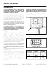
1. Mount plate
2. Electronic control unit
3. Sonic boom fuse block
4. Relay (6 used)
5. Cap screw (4 used)
6. Lock washer (4 used)
7. Nut (4 used)
Figure 10
2
3
6
1
5
7
4
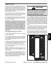
Figure 11
86
85
87A 87
30
2
1
3
4
1. Coil terminal
2. Common terminal
3. Normally closed term.
4. Normally open term.
1
Electrical
System