


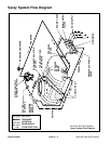
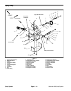
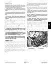

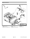

Removal (Fig. 6)
IMPORTANT: Make sure to neutralize and remove
chemicals from pump and hoses before loosening
and removing spray system components.
1. Park machine on a level surface, stop engine, en-
gage parking brake, and remove key from the ignition
switch.
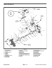
2. Loosen hose clamp that secures suction hose (item
28) to hosebarb (item 25). Pull suction hose from hose
-
barb.
3. Loosen hose clamp that secures pressure hose
(item 11) to hosebarb (item 8). Pull pressure hose from
hosebarb.
4. Remove PTO driveshaft (item 17) from output shaft
of transaxle PTO assembly.
5. Remove four (4) flange head screws and flange nuts
that secure pump assembly to pump mount bracket.
6. Remove pump assembly (with PTO driveshaft and
drive shrouds attached) from machine.
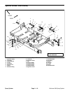
7. Remove four (4) flange head screws and flange nuts
that secure pump drive shrouds (item 13) to shroud
bracket (item 14). Remove pump drive shrouds.
8. Loosen two (2) set screws (item 16) that secure PTO
drive shaft to pump shaft. Separate PTO drive shaft from
pump. Locate and remove key from pump shaft.
9. As needed, remove pressure and suction compo-
nents from pump using Figure 6 as a guide. Discard any
removed o–rings and gaskets.
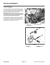
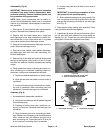
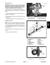
Installation (Fig. 6)
NOTE: Coat all o–rings with vegetable oil before instal-
lation to reduce the chance of damage during assembly.
1. Apply thread sealant to threads of pressure tee fit-
ting, elbow (pressure), and suction tee fitting. Position
new o–rings and gaskets on suction and pressure fit
-
tings that were removed during disassembly.
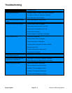
2. Install suction tee fitting and suction dampener to
pump inlet. Orientate tee toward right side of machine
(Fig. 7).
3. Install elbow (pressure), pressure tee fitting, and
pressure dampener to pump outlet. Orientate elbow to
-
ward right side of machine (Fig. 7).
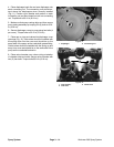
4. Remove set screws (item 16) from PTO driveshaft.
Clean threads of set screws and set screw threads in dri
-
veshaft.
5. Apply anti–seize lubricant to pump shaft. Position
square key in pump shaft and slide PTO driveshaft fully
onto pump shaft.
6. Apply Loctite #242 (or equivalent) to threads of set
screws. Install set screws into PTO drive shaft to secure
PTO shaft to pump shaft.
7. Position pump drive shrouds (item 13) to shroud
bracket (item 14). Install four (4) flange head screws and
flange nuts to secure shrouds to bracket.
8. Position pump on pump mount bracket. Install flange
head screws and flange nuts to pump and mount brack
-
et. Secure pump to mount bracket.
9. Attach PTO driveshaft to output shaft of transaxle
PTO assembly.
10.Install pressure and suction hoses to correct barb fit-
tings. Secure hoses with hose clamps.
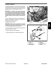
2
1
Figure 7
1. Elbow (pressure) 2. Suction hose
Spray
System
Workman 200 Spray System
Page 3 – 11
Spray System