


IMPORTANT: Make sure to remove and neutralize
chemicals from spray components before disas
-
sembly. Wear protective clothing, chemical resist-
ant gloves, and eye protection during repair.
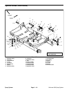
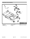
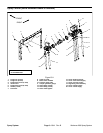
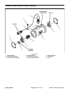
Removal (Fig. 21)
1. Park machine on a level surface, stop engine, en-
gage parking brake, and remove key from the ignition
switch.
2. Label hoses for proper installation after repairs are
completed. Loosen hose clamps and disconnect hoses
from spray control.
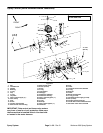
3. Unplug electrical connectors from rate control motor,
flowmeter, and three (3) boom valve motors from ma
-
chine electrical harness.
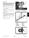
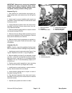
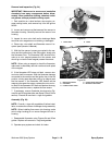
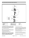
4. Remove pressure gauge tube from coupler on back
of flowmeter housing (Fig. 23).
5. Remove three (3) flange head screws that secure
spray control assembly to valve mounting bar. Remove
spray control assembly from machine.
6. Remove spray control components as required us-
ing Figure 21 as a guide. Discard all removed o–rings
and gaskets.
Assembly (Fig. 21)
NOTE: Coat all o–rings with vegetable oil before instal-
lation to reduce the chance of damage during assembly.
1. Install spray control components using Figure 21 as
a guide. Replace all removed o–rings and gaskets.
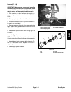
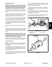
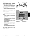
2. Before installing rod (Item 2) into assembly, thread
nut (item 1) fully onto rod end that has fewer threads.
Make sure that o–ring (Item 3) is not damaged during
installation over rod. To secure assembly, torque nut 71
in–lb (8 N–m).
3. Position spray control assembly to valve mounting
bar and secure with three (3) flange head screws.
4. Install hoses to correct locations on spray control as-
sembly. Secure hoses with hose clamps.
5. Install pressure gauge tube to coupler on back of
flowmeter housing (Fig. 23).
6. Plug electrical connectors from rate control motor,
flowmeter, and three (3) boom valve motors to machine
electrical harness.
7. Operate spray system and check for leaks.
1
2
5
3
6
4
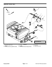
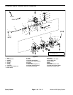
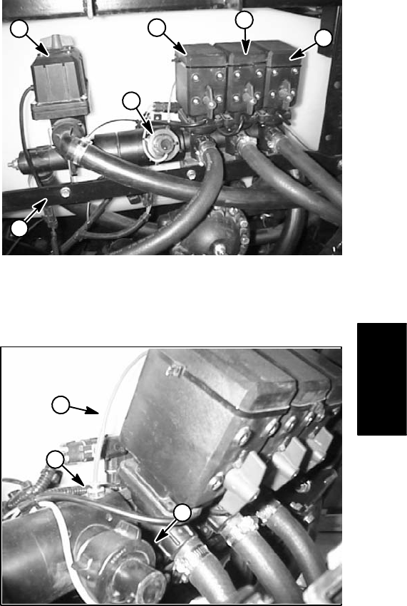
Figure 22
1. Rate control motor 4. Center boom valve motor
2. Flowmeter 5. RH boom valve motor
3. LH boom valve motor 6. Valve mounting bar
1
2
3
Figure 23
1. Flowmeter 3. Coupler
2. Pressure gauge tube
Spray
System
Workman 200 Spray System
Page 3 – 23
Spray System