


Workman 200 Spray System
Page 3 – 37
Spray System
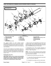
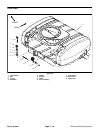
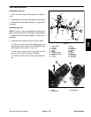
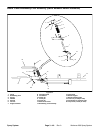
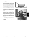
Disassembly (Fig. 38)
IMPORTANT: Make sure to remove and neutralize
chemicals from tank and spray components before
disassembly. Wear protective clothing, chemical re-
sistant gloves, and eye protection during repair.
1. Park machine on a level surface, stop engine, en-
gage parking brake, and remove key from the ignition
switch.
2. Drain spray tank (see Operator’s Manual).
3. Raise tank lid and remove strainer basket to gain ac-
cess to chain (item 7) that connects drain handle (item
1) to plunger in drain assembly (item 8). Disconnect
chain from drain handle.
4. If necessary, remove drain handle and bulkhead us-
ing Figure 38 as a guide.
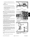
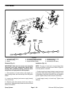
5. If necessary, remove drain assembly from tank:
A. Loosen hose clamp and slide drain hose from
drain assembly hosebarb.
B. Remove fork from drain assembly to allow hose-
barb to be removed from drain assembly.
C. Remove bulkhead nut that secures drain assem-
bly to spray tank.
D. Lift drain assembly from bottom of tank.
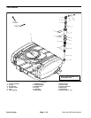
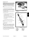
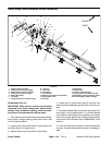
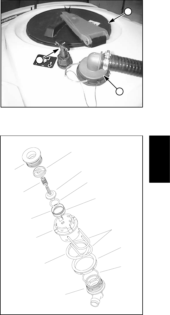
6. Disassemble drain assembly using Figure 40 as a
guide.
7. Discard all removed o–rings and gaskets.
Assembly (Fig. 38)
NOTE: Coat all o–rings with vegetable oil before instal-
lation to reduce the chance of damage during assembly.
1. Assemble drain tube using Figures 38 and 40 as
guides. Replace all removed o–rings and gaskets.
2. Hosebarb of drain assembly should be orientated to-
ward the rear of the spray tank. Make sure that clear-
ance exists between drain assembly and sprayer frame.
3. Check spray tank for leaks.
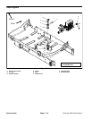
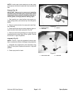
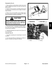
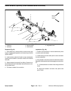
1. Tank drain
2. Suction strainer
3. Tank lid
Figure 39
1
2
3
1. Adapter
2. Plunger holder
3. Spring
4. Drain plunger
5. O–ring
6. Drain seat
7. O–ring
8. Drain bulkhead
9. Fork
10. Gasket
11. Bulkhead nut
12. O–ring
13. Hosebarb
Figure 40
9
7
8
10
3
1
2
4
6
5
11
12
13
Spray
System