


1
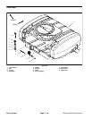
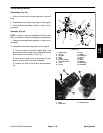
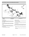
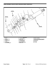
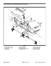
Assembly (Fig. 47)
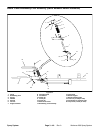
1. If pivot bracket (item 11) was removed from machine,
lightly lubricate bushings (item 12) with motor oil before
assembly. Connect boom actuator (not shown) to pivot
bracket (see Boom Actuator Installation (Machines with
Serial Numbers Above 260000000) in this section).
2. Make sure that hinges (item 1) are securely fastened
to pivot bracket (item 11) and boom (item 5). The boom
hinge uses four (4) backing plates between the boom
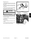
2
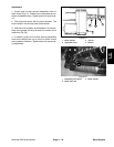
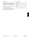
UP
Figure 48
and flange nuts.
1. Rubber boot 2. Rib
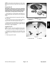
3. Position boom hinge to pivot bracket hinge. Make
sure that rubber boots (item 2) are placed at hinge junc
-
tions and that rib on boots are toward the top of the boom
(Fig. 48).
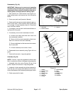
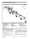
4. Insert two (2) cap screws (item 9) through flat wash-
ers (item 10) and hinges. Place tube (item 17), break-
away spring (item 19), spring retainer (item 18) and lock
nut (item 8) on each cap screw. Make sure that shoulder
on spring retainer fits into breakaway spring.
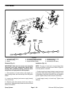
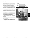
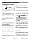
5. Tighten lock nuts so there is 1.560” (39.6 mm) be-
tween the face of the spring retainer and the hinge cast-
ing (Fig. 49).
6. Connect supply hose to tee fitting on spray boom and
secure with hose clamp.
7. Lubricate grease fittings on boom hinge (see Opera-
tor’s Manual).
Figure 49
1.560”
(39.6 mm)
Spray
System
Workman 200 Spray System
Page 3 – 43
Rev. A
Spray System