


Workman 200Ultra Sonic Boom System (Rev. C) Page 3.2 -- 20
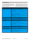
Diagnostic Display
The Ultra Sonic Boom System is equipped with the Toro
electronic controller (TEC) which controls machine son-
ic boom electrical functions. The TEC monitors various
input switches (e.g. sonic boom switch, boom lift
switches, sonic boom sensors) and energizes outputs
(e.g. boom actuators, diagnostic lamp) for appropriate
machine functions.
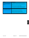
For the TEC to control the machine as desired, each of
the inputs (switches and sensors) and outputs (e.g.
boom actuators) must be connected and functioning
properly.
The Diagnostic Display (see Special Tools in this chap-
ter)isatooltohelpthetechnician verifycorrectelectrical
functions of the machine.
IMPORTANT: The Diagnostic Display must not be
left connected to the machine. It is not designed to
withstand the environment of the machine’s every
dayuse. Whenuse oftheDiagnostic Displayiscom-
pleted, disconnect it from the machine and recon-
nect loopback connectorto harnessconnector. The
machine will not operate without the loopback con-
nector installed on the harness. Store the Diagnos-
tic Display in a dry, secure, indoor location and not
on machine.
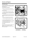
Verify Diagnostic Display Input Functions
1. Parkmachineon alevelsurface,stop theengineand
apply the parking b rake.
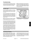
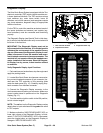
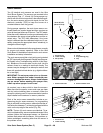
2. Locate Ultra Sonic Boom wire harness communica-
tion port and loopback connector (6 pin connector) loc-
ated near the TEC controller on the mounting plate
under the dash panel (Fig. 10). Carefully unplug loop-
back connector from harness connector.
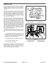
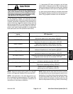
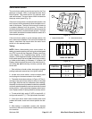
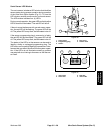
3. Connect the Diagnostic Display connector to the
wire harness communication port connector. Make sure
correct overlay decal is positioned on the Diagnostic
Display (Fig. 11).
4. Turn the machine ignition switch to the ON position,
but do not start e ngine.
NOTE: The red text on the Diagnostic Display overlay
decal refers to input switches and the green text refers
to TEC outputs.
5. Make sure that the “INPUTS DISPLAYED” LED, on
lower right column of the Diagnostic Display, is illumi-
nated. If “OUTPUTS DISPLAYED” LED is illuminated,
press the toggle button on the Diagnostic Display to
change to “INPUTS DISPLAYED” LED.
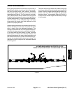
Figure 10
1. TEC controller location
2. Loopback connector
3. Diagnostic tether cap
1
2
3
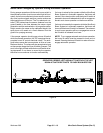
Figure 11
119--9431