


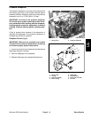

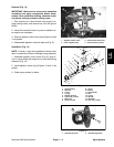
Disassembly (Fig. 8)
IMPORTANT: Make sure to remove and neutralize
chemicals from pump before disassembly. Wear
protective clothing, chemical resistant gloves, and
eye protection during pump repair.
NOTE: Many pump components can be easily re-
versed. During disassembly, make note of component
position (e.g. crankshaft, valve chamber) to assure cor
-
rect assembly.
1. Remove two (2) hex bolts that retain valve chamber
to pump. Separate valve chamber from pump.
2. Remove inlet and outlet valves and o–rings from
each diaphragm cover. Note orientation of valves. Dis
-
card valves and o–rings. Clean valve and o–ring seats
in the valve chambers and diaphragm covers.
3. Remove hex bolts that secure diaphragm covers to
pump. Remove diaphragm covers.
4. Remove hex bolt, washer, nylon washer, diaphragm,
and diaphragm back disc from each connecting rod.
Discard diaphragms.
5. Remove five (5) hex bolts and nuts that secure pump
casing halves together. Note location of two (2) longer
hex bolts with washers. Carefully separate pump casing
halves.
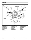
6. Clean grease from bottom of housing and check con-
dition of bearings on crankshaft. If bearings require re-
placement, remove and disassemble crankshaft:
A. Remove crankshaft assembly from pump casing.
B. Slide felt seal and dust plate from both ends of
crankshaft.
C. Loosen hex bolt and hex nut that secure connect-
ing rods to crankshaft. Slide connecting rods from
crankshaft. Press ball bearings from crankshaft.
Assembly (Fig. 8)
1. If disassembled, reassemble crankshaft.
A. Hand pack new bearings with #2 general purpose
lithium base grease.
B. Pressing on bearing inner race, install two con-
necting rod and two crankshaft ball bearings onto
crankshaft.
C. Slide connecting rods onto connecting rod bear-
ings. Offsets of the connecting rods should face each
other. Install hex bolt, flat washers, and hex nut to
each connecting rod. Torque hex nuts to 25 ft–lb (34
N–m) to secure connecting rods to crankshaft.
D. Position dust plate and felt seal on both ends of
crankshaft.
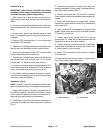
IMPORTANT: If connecting rod position is incor-
rect, pump will not operate properly.
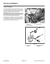
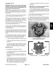
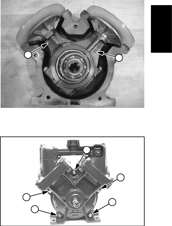
E. Slide crankshaft assembly into pump casing. The
rear connecting rod should be positioned to the left
side and the connecting rod closest to you to the right
side (Fig. 9).
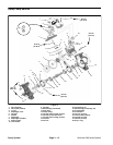
2. Place second pump casing onto assembly. Pump
casing surfaces should mate together.
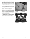
3. Install three (3) shorter (30 mm) bolts and two (2) lon-
ger (55 mm) bolts with washers into pump casing as-
sembly (Fig. 10). Thread hex nuts onto bolts but do not
fully tighten. Check that crankshaft turns freely.
1
2
Figure 9
1. Closest connecting rod (to right side)
2. Rear connecting rod (to left side)
1
2
2
1
1
Figure 10
1. Hex bolt (30 mm long) 2. Hex bolt (55 mm long)
Spray
System
Workman 200 Spray System
Page 3 – 13
Spray System