


Rev. B
Workman 200 Spray System Page 3.1 -- 25 Sonic Boom System (Optional Kit)
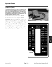
Sonic Sensor
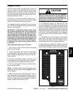
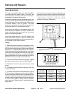
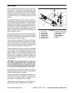
Two (2) identical sonic sensors are used in the Sonic
Boom System. The sensors are mounted to the spray
booms(Fig.13).During sprayeroperation withthesonic
modeswitchintheautomaticposition,thesonics ensors
will provide inputs for the electronic control unit (ECU)
to keep the booms at a constant distance from the
ground.
During sprayer operation, the sonic boom sensor con-
tinually sends an impulse signal and then receives an
echo as the signal bounces off the turf. The ECU estab-
lishesthe sensordistance fromthe groundbased onthe
time between the sensor signal generation and the re-
ceived echo. The ECU then determines if the boom
height is different than the calibrated height and, if nec-
essary, energizes the appropriate boom actuator to
change the boom height.
Sensors and protection tubes should be rotated above
parallel with the ground for proper sonic sensor opera-
tion.RefertotheSonic BoomKitInstallationInstructions
for sonic sensor setup information.
The sonic sensor includes a LED that should be illumi-
nated during sprayer operation regardless of whether
the sonic mode switch is in manual or automatic mode.
The intensity of the LED can be used to assure that the
sensor is properly adjusted on the spray boom.
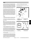
The sonic sensors and their circuit wiring can be tested
as ECU inputs w ith the Diagnostic Display (see Diag-
nostic Display in the Troubleshooting section of this
chapter).Becauseofthesolidstatec ircuitry builtintothe
sensors, there is no method to test them directly. The
sensors may be damaged if an attempt is made to test
them with an electrical test device (e.g. digital multime-
ter or test light)
IMPORTANT: Do not spray water at or on the sen-
sors. Water sprayed under even household pres-
sure can damage the sensor. Always install sensor
cover (item 7) on sensor before washing the spray-
er. Also, install cover when sprayer is not in use.
As required, use a damp cloth to clean the sensors.
Make sure thatthe sensor covers (item7) are cleanand
dry before installing them on sensors.
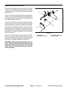
The patch (item 13) that is adhered to the sensor is de-
signed to allow moisture to escape from inside the sen-
sor housing. The patch should be replaced if it is
deteriorated or has loosened from the sensor.
Inspectthefoamsensor filter(item11)fordamageorex-
cessive debris buildup. Replace filter if necessary.
1. Sonic sensor
2. Sensor bracket
3. Screw (2 used)
4. Protection tube
5. U--bolt (4 used)
6. Lock nut (8 used)
7. Sensor cover
8. Spray boom (RH shown)
9. Lock washer (2 used)
10. Nut (2 used)
11. Foam sensor filter
12. Sensor shield
13. Patch
Figure 13
2
3
6
8
9
10
1
5
7
4
11
12
13