


Workman 200Ultra Sonic Boom System (Rev. C) Page 3.2 -- 30
Relays
The Ultra Sonic Boom System uses four (4) identical re-
lays to control the boom actuators and ultimately the
boom height. Two(2) ofthe relayscontroltheright boom
actuator and the other two (2) relays control the left
boom actuator. The Toro electronic controller (TEC)
controls the operation of the relays. The appropriate
relay isenergized by the TEC to allow currentflow to the
boom actuators in the proper direction so that the actu-
ator extends (boom raise) or retracts (boom lower).
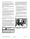
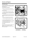
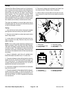
Therelaysarelocatedonamountplateundertheve-
hicledashpanel (Fig.22) andcanbeidentifiedby alabel
on the wire harness connector.
Testing
1. Park vehicle on a level surface, stop engine, engage
parking brake and remove key from ignition switch.
2. Remove mount plate from under dash panel to allow
easier relay access.
3. Locate relay to be tested and disconnect wire har-
ness connector from relay. Remove relay from mount
plate for testing.
NOTE: Prior to taking small resistance readings with a
digital multimeter, short the meter test leads together.
The meter will display a small resistance value (usually
0.5 ohms or less). T his resistance is due to the internal
resistance of the meter and test leads. Subtract this val-
ue from from the measured value of the component you
are testing.
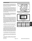
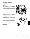
4. Using a multimeter, verify that coil resistance be-
tween terminals 85 and 86 is from 71 to 88 ohms.
5. Connectmultimeter (ohmssetting) leadsto relayter-
minals 30 and 87. Ground terminal 86 and apply +12
VDC t o terminal 85. The relay should make and break
continuity between terminals 30 and 87 as +12 VDC is
applied and removed from terminal 85.
6. Disconnect voltage from terminal 85 and multimeter
lead from terminal 87.
7. Connectmultimeter (ohmssetting) leadsto relayter-
minals 30 and 87A. Apply +12 VDC to terminal 85. The
relay should make and break continuity between termi-
nals 30 and 87A as +12 VDC is applied and removed
from terminal 85.
8. Disconnect voltage and multimeter test leads from
the relay terminals. Replace relay if necessary.
9. Secure relay to mount plate and connect wire har-
ness connector to relay. Secure mount plate tomachine
frame.
1. Mount plate
2. U--bolt clamp (2 used)
3. Relay (4 used)
4. Cap screw (4 used)
5. Lock washer (4 used)
6. Nut (4 used)
Figure 22
1
2
3
6
5
4
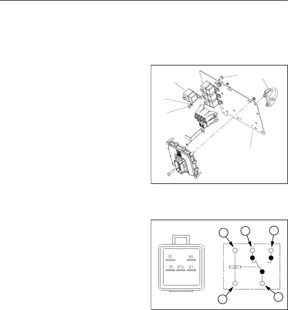
Figure 23
86
85
87A 87
30
2
1
3
4
1. Coil terminal
2. Common terminal
3. Normally closed term.
4. Normally open term.
1