


Rev. B
Workman 200 Spray SystemPage 3 -- 2 6Spray System
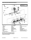
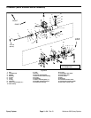
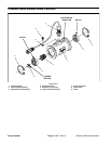
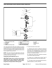
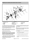
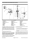
Rate Control Motor (Serial Numbers Below 290999999)
1. Phillips head screw (5 used)
2. Lock washer
3. Hand grip
4. O--ring
5. Phillips head screw (4 used)
6. Rate control motor assembly
7. Gasket
8. Phillips head screw (4 used)
9. Rate valve spindle section
10. Rate control valve housing
11. O--ring
12. Cone
13. Control valve
14. Seal
Figure 27
3
7
4
8
11
12
14
10
13
9
6
5
2
1
1
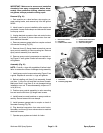
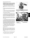
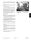
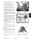
The rate control motor allows the operator to vary the
spray applicationrate. Thepressure increase/decrease
switch on the spray console energizes the rate control
motor whichadjusts the valveopening and allowssome
flow to bypass the spray booms.
NOTE: The rate control motor affects flow to all spray
booms. Therefore,a problemwith therate controlmotor
will affect all booms and nozzles.
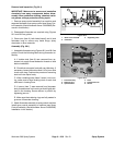
Disassembly and Inspection (Fig. 27)
IMPORTANT: Make sure to remove and neutralize
chemicals from spray components before disas-
sembly. Wear protective clothing, chemical resist-
ant gloves, and eye protection during repair.
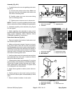
1. To remove the rate control motor:
A. Adjust the rate control to maximum to allow the
rate control motor spring to relax. This can be done
with either the increase/decrease s witch on the
spray consoleor byrotating thehand grip onthe mo-
tor fully in a clockwise direction.
B. Unplug rate control motor electrical connector
from machine electrical harness.
C. Loosen four (4) phillips head screws (item 5)
evenly to allow removal of the rate control motor.
D. The inside ofmotor housing should be free of ex-
cessive moisture, corrosion, and dirt.