


Workman 200 Ultra Sonic Boom System (Rev. C)Page 3.2 -- 21
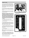
CAUTION
WhentestingTECinputs withtheDiagnostic Dis-
play, boom actuators may be energized causing
the spray booms to move. Be cautious of poten-
tial sprayer component movement while verify -
ing inputs with the Diagnostic Display.
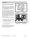
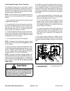
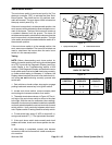
6. The Diagnostic Display will illuminate the LED
associatedwitheachof theinputswhenthat inputswitch
is closed. Individually,change each of theswitches from
opento closed (e.g.toggle sonicboomswitch), andnote
that the appropriate LED on the Diagnostic Display will
illuminate when the corresponding switch is closed. Re-
peat on each switch that is possible to be changed by
hand (see Inputs and LED Operation chart below).
7. If appropriate LED does not toggle on and off when
switch state is changed, perform test of switch and/or
check all wiring and connections to that switch. Replace
any defective switches and repair any damaged wiring.
8. After input functions testing is complete, disconnect
the Diagnostic Display connector from the harness con-
nector. Plug loopback connector into wire harness.
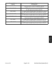
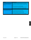
Diagnostic Display
Inputs
Diagnostic Display
LED Operation
AUTO MODE Sonic boom switch in auto position: LED ON
Sonic boom switch not in auto position: LED OFF
RIGHT RAISE Right boom lift switch in raise position: LED ON
Right boom lift switch not in raise position: LED OFF
RIGHT LOWER Right boom lift switch in lower position: LED ON
Right boom lift switch not in lower position: LED OFF
LEFT RAISE Left boom lift switch in raise position: LED ON
Left boom lift switch not in raise position: LED OFF
LEFT LOWER Left boom lift switch in lower position: LED ON
Left boom lift switch not in lower position: LED OFF
RETRIEVE FAULTS Diagnostic shunt wires are connected for fault retrieval: LED ON
Diagnostic shunt wires are not connected: LED OFF
LEFT SENSOR FAULT The TEC has detected an invalid reading from left sensor: LED ON
Left sensor operating normally: LED OFF
RIGHT SENSOR FAULT The TEC has detected an invalid reading from right sensor: LED ON
Right sensor operating normally: LED OFF
KEY RUN Ignition key is in ON position: LED ON
Ignition key is in OFF position: LED OFF
NOTE: When the vehicle ignition switch is in the OFF
position, all Diagnostic Display LED’s should be OFF.
NOTE: Initial calibration of the Ultra Sonic Boom sen-
sors is required for proper operation of TEC inputs. Re-
fer to your Sonic Boom Kit Installation Instructions for
information on initial sensor calibration.
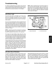
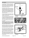
NOTE: Right and left side Ultra Sonic Boom sensors
are identical so they can be exchanged to as sist in trou-
bleshooting. Ifa problem follows the exchanged sensor,
an electrical problem likely exists with the sensor. If the
problem remains unchanged, something other than the
sensoris theproblem source (e.g.switch, circuitwiring).
Ultra Sonic
Boom System