


Workman 200Ultra Sonic Boom System (Rev. C) Page 3.2 -- 28
Sonic Sensors
Two (2) identical sonic sensors are used in the Ultra
Sonic Boom System. The sensors are mounted to the
spray booms (Figs. 17, 18 and 19). During sprayer op-
eration withthe sonicboom switchin theautomaticposi-
tion, the sonic sensors will provide inputs for the Toro
electronic controller (TEC) to keep the booms at a
constant distance from the ground.
During sprayer operation, the sonic boom sensor con-
tinually sends an impulse signal and then receives an
echo as the signal bounces off the turf. The TEC estab-
lishesthe sensordistance fromthe groundbased onthe
time between the sensor signal generation and the re-
ceived echo. The TEC then determines if the boom
height is different than the calibrated height and, if nec-
essary, energizes the appropriate boom actuator(s) to
change the boom height.
Sensors shouldbe s ecuredto thespray boomscorrectly
for proper sonic sensor operation. Refer to the Ultra
Sonic Boom Kit Installation Instructions forsonic sensor
installation and setup information.
The sonic sensors and their circuit wiring can be tested
asTEC inputswiththeDiagnosticDisplay (seeDiagnos-
tic Display in the Troubleshooting section of this chap-
ter). Because of the solid state circuitry built into the
sensors, there is no method to test them directly. The
sensors may be damaged if an attempt is made to test
them with an electrical test device (e.g. digital multime-
ter or test light)
IMPORTANT: Do not spray water at or on the sen-
sors. Water sprayed even under household pres-
sure can damage the sensor. Always install sensor
cap on sensor before washing the sprayer. Also,
install cap when sprayer is not in use.
As required, use a damp cloth to clean the sensors.
Make sure that the sensor covers and caps are clean
and dry before installing them on sensors. When the
sprayer is not beingused, itisrecommendedto havethe
caps installed on the sensors for sensor protection.
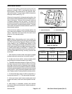
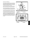
Each of the sonic sensor assemblies includes a pro-
gramming plug for sensor accuracy. If a programming
plug is removed from the sensor, make sure that the ar-
row below thesideways T on the plug is aligned with the
notch on the top edge of the sensor (Fig. 20).
NOTE: The two (2) sonic sensors are identical. To as-
sistin troubleshooting,sensorscanbe exchanged.Ifthe
problem follows the exchanged sensor, an electrical
problem likely exists with the se nsor. If the problem re-
mains unchanged, something other than the sensor is
the problem source.
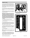
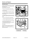
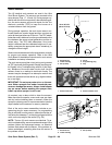
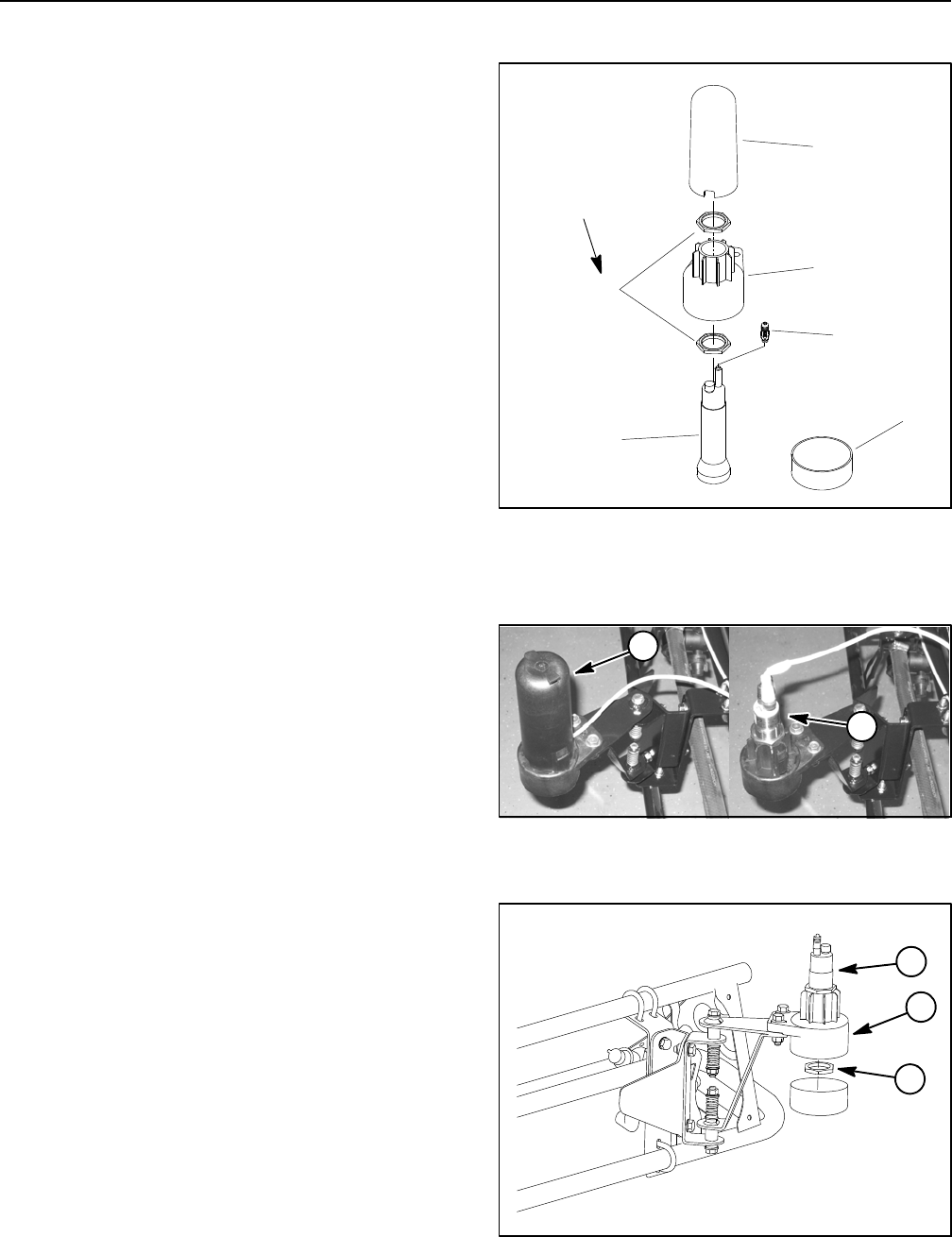
1. Sonic sensor
2. Lower housing
3. Nut (2 used)
4. Cover
5. Programming plug
6. Cap
Figure 17
4
6
1
5
2
3
14 to 16 ft--lb
(19to21N--m)
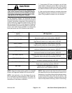
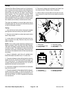
1. Sensor with cover 2. Sensor without cover
Figure 18
1
2
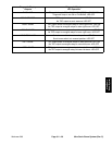
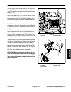
1. Sonic sensor
2. Lower housing
3. Nut (2 used)
Figure 19
1
2
3