


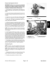
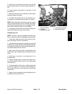


4. Remove rear housing cover from boom valve motor
to inspect motor components.
A. Cam should be tight on shaft. Cam surface
should be free of wear and/or scoring.
B. The inside of motor housing should be free of ex-
cessive moisture, corrosion, and dirt.
C. The cam bearing surface in the housing cover
should be inspected for excessive wear.
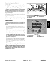
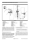
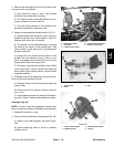
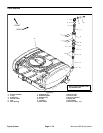
5. Inspect and disassemble spindle section (Fig. 31).
A. Inspect spindle roller surface for wear or scoring.
Check that spindle roller rotates freely on roller pin.
Replace roller and/or pin as required.
B. The spindle can be disassembled by removing
the screw at the bottom of the spindle shaft. Take
note of washer, spring, seat, and o–ring locations as
spindle is removed.
C. Inspect the cone located at the bottom of the
spindle. The cone should be free of nicks or worn
spots. A damaged cone will allow flow to the boom
bypass rather than to the spray boom.
D. The seat o–rings allow the spindle to shut off flow
to the spray boom. If boom nozzles leak when the
boom is shut off, the seat and seat o–rings should be
inspected carefully.
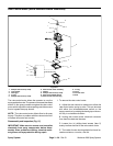
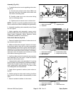
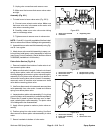
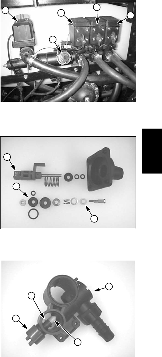
6. If leakage occurs from balancing valve knob at bot-
tom of boom valve manifold (Fig. 32):
A. Carefully remove roll pin that secures balancing
valve to knob.
B. Remove knob from manifold. Remove and dis-
card o–ring.
C. Inspect seating surfaces of manifold and balanc-
ing valve. Clean or replace components as needed.
Assembly (Fig. 29)
NOTE: Coat all o–rings with vegetable oil before instal-
lation to reduce the chance of damage during assembly.
1. Replace all removed o–rings.
2. If boom valve manifold was disassembled (Fig. 32):
A. Install o–ring, balancing valve, and knob to man-
ifold.
B. Secure balancing valve to knob by carefully
installing roll pin.
1
2
5
3
4
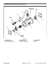
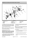
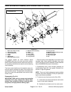
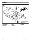
Figure 30
1. Rate control motor 4. Center boom valve motor
2. Flowmeter 5. RH boom valve motor
3. LH boom valve motor
1
2
3
Figure 31
1. Spindle roller 3. Seat
2. Cone
4
3
1
2
Figure 32
1. Boom valve manifold 3. Balancing valve knob
2. Balancing valve 4. Roll pin
Spray
System
Workman 200 Spray System
Page 3 – 29
Spray System