


Rev. B
Workman 200 Spray SystemPage 3.1 -- 24Sonic Boom System (Optional Kit)
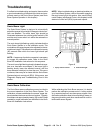
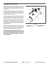
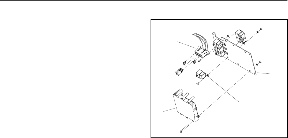
Electronic Control Unit (ECU)
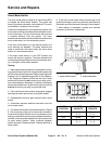
The Sonic Boom System uses an electronic control unit
(ECU) to control electrical system operation. The ECU
is attached to a mounting plate under the vehicle dash
panel (Fig. 12).
Power is provided to the ECU when the vehicle ignition
switchis ON.A5amp fuseprovidescircuit protectionfor
this logic power to the ECU. The fuse is located in the
Sonic Boom System fuse block.
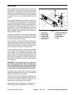
The ECU monitors the s tates of the following compo-
nentsasinputs:the sonicmodeswitch,thetwo (2)boom
actuator switches and the two (2) boom sonic sensors.
The ECU controls electrical output to the s onic boom
light and the six (6) relays that are part of the Sonic
Boom System. Circuit protection for the ECU outputs is
provided by a 10 amp fuse located in the Sonic Boom
System fuse block.
Because of the solid state circuitry built into the ECU,
there is no method to test it directly. The ECU may be
damagedif anattemptis madetotest itwithanelectrical
test device (e.g. digital multimeter or test light).
IMPORTANT: Before performing welding on thema-
chine, disconnect both cables from the battery and
disconnect wire harness connector from the ECU.
These steps will prevent damage to the machine
electrical system.
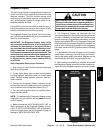
1. Mount plate
2. Electronic control unit
3. Sonic boom fuse block
4. Relay (6 used)
Figure 12
2
3
1
4