


Rev. B
Page 3 -- 23.2Workman 200 Spray System Spray System
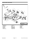
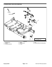
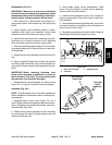
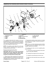
Disassembly (Fig. 23.1)
IMPORTANT: Make sure to remove and neutralize
chemicals from tank and spray components before
disassembly.Wearprotectiveclothing, chemicalre-
sistant gloves, and eye protection during repair.
1. Park machine on a level surface, stop engine, en-
gage parking brake, and remove key from the ignition
switch.
2. Label all spray control assembly hoses for proper
installation after repairs are completed. Loosen hose
clamps and disconnect hoses from spray control.
3. Label all wire harness leads for assembly purposes.
Disconnect wire harness connectors from regulating
valve, flowmeter and three (3) boom valve motors.
4. Removepressure gaugetube(item 10)from coupler
onpressuregaugeport onrightside ofboomvalveman-
ifold assembly.
5. Supportspraycontrolassembly topreventitfromfal-
ling.
6. Remove eight (8) flange head screws, flat washers
and flange nuts that secure spray control assembly to
valve mount. Remove spray control assembly from ma-
chine.
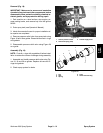
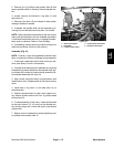
IMPORTANT: Before removing flowmeter from
spray control assembly, note direction of arrow on
top of flowmeter (Fig. 23.3). The arrow should point
toward boom valve manifold assembly.
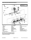
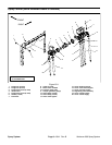
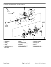
7. Separate spray control assembly as required using
Figure 23.1 as a guide. Discard all removed gaskets.
Assembly (Fig. 23.1)
NOTE: Coat all gaskets and o--rings with vegetable oil
before installation to reduce the chance of damage dur-
ing assembly.
1. Assemble spray control using Figure 23.1 as a
guide. Replace all removed gaskets. Make sure that ar-
row on flowmeter body points toward boom valve man-
ifold assembly (Fig. 23.3).
2. Position spray control assembly to valve mounting
bar and secure with eight (8) flange head screws, flat
washers and flange nuts.
3. Using labels placed during disassembly, install
hoses to correct locations on spray control assembly.
Secure hoses with hose clamps.
4. Install pressure gauge tube (item 10) to coupler on
pressure gauge port on right side of boom valve man-
ifold assembly.
5. Usinglabels placedduring disassembly,secure wire
harness connectors to regulating valve, flowmeter and
three (3) boom valve motors.
6. Operatespraysystemandcheck forleaks.Repairall
leaks before returning the s prayer to service.
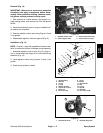
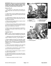
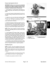
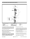
1. Boom valve manifold
2. Flowmeter
3. Regulating valve
Figure 23.2
2
1
3
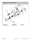
Figure 23.3
NOTE ARROW
DIRECTION
TO BOOM
VALVE
MANIFOLD
FROM
REGULATING
VALVE
Spray
System