


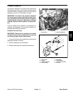
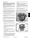

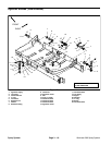
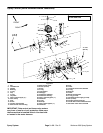
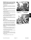

Removal (Fig. 13)
IMPORTANT: Make sure to remove and neutralize
chemicals from spray components before disas
-
sembly. Wear protective clothing, chemical resist-
ant gloves, and eye protection during repair.
1. Park machine on a level surface, stop engine, en-
gage parking brake, and remove key from the ignition
switch.
2. Label disconnected hoses for proper installation af-
ter repairs are completed.
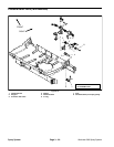
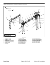
3. Remove agitation control valve using Figures 13 and
14 as guides.
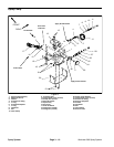
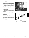
4. Disassemble agitation valve as required (Fig 15).
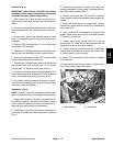
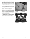
Installation (Fig. 13)
NOTE: Coat all o–rings with vegetable oil before instal-
lation to reduce the chance of damage during assembly.
1. Assemble agitation control valve (Fig 15). Align ar-
row on valve handle with large hole in valve ball during
assembly (Fig. 16).
2. Install agitation valve using Figures 13 and 14 as
guides.
3. Check spray system for leaks.
1
2
3
4
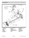
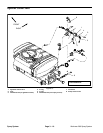
Figure 14
1. Agitation control valve 3. Suction hose (from tank)
2. Control bypass hose 4. Suction hose (to pump)
1
2
5
3
4
2
3
15
5
9
13
10
12
11
14
6
7
8
4
7
16
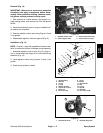
Figure 15
1. Valve housing
9. Screw
2. Ball seat
10. Button
3. O–ring
11. Valve handle
4. O–ring
12. Disc
5. Washer (8 used)
13. O–ring
6. Cap screw (4 used)
14. Spindle
7. End cover
15. Valve ball
8. Screw (4 used)
16. Lock nut (4 used)
Spray
System
2
1
Figure 16
1. Valve handle arrow 2. Valve ball large hole
Workman 200 Spray System
Page 3 – 17
Spray System