


Rev. B
Page 3 -- 27.2Workman 200 Spray System Spray System
Assembly (Fig. 28.1)
1. To installvalve motorcover toregulating valve motor
(Fig. 28.3):
A. Connect cover wires to motor wires. Make sure
that cover wire color is the same as the motor wire
color when connecting wires.
B. Carefully rotate cover onto valve motor taking
care to not damage wires.
C. Tighten screws to secure cover to valve motor.
NOTE: CoatallO--ringswith vegetableoilbeforeinstal-
lation toreducethe chanceof damageduringassembly.
2. Assemble regulating valve assembly using Figure
28.1 as a guide.
3. Attach regulating valve assembly to spray control
and then installspray control assembly tomachine (see
Spray Control Assembly (Serial Numbers Above
310000000) Installation in this section).
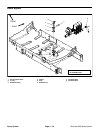
Piston Valve Service (Fig. 28.4)
1. Remove hosebarb from bottom of valve motor to al-
low access to piston valve.
2. Make sure that valve is closed. If valve is not closed,
spring above piston valve will be under compression
and maydamagevalve motoror pistonvalve duringdis-
assembly. End of piston valve will extend into bottom of
valve motor housing when valve is closed. Ifnecessary,
reconnect motor to machine wire harness and close
valve before removing piston valve.
3. Use 3mm allen wrench to loosen and remove piston
valve assembly from valve motor. Locate and retrieve
spring from above piston valve.
4. Inspectsealsonpistonvalveassembly.O--ringintop
groove ofpiston valve assemblyis available separately.
If lower two (2) seals in piston valve are worn or dam-
aged, replace piston valve assembly. The piston valve
is not designed to be disassembled.
5. Apply silicone grease to seals on piston valve as-
sembly.
6. Position spring into valve motor housing. Use 3mm
allen wrench to secure piston valve assembly to valve
motor.
7. Secure hosebarb to bottom of valve motor.
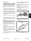
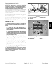
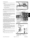
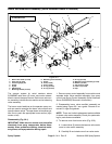
1. Boom valve manifold
2. Flowmeter
3. Regulating valve
Figure 28.2
2
1
3
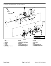
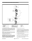
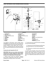
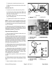
1. Valve motor assembly
2. Valve motor cover
3. Wire connector
4. Socket screw (4 used)
5. Phillips screw (2 used)
Figure 28.3
1
2
5
4
3
3
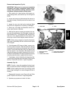
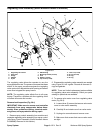
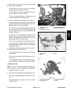
1. Valve motor assembly
2. Piston valve assembly
3. Valve seal
4. Spring
5. Valve motor cover
Figure 28.4
2
1
3
4
5
Spray
System