


Rev. B
Page 3 -- 25.2Workman 200 Spray System Spray System
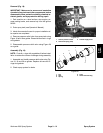
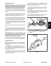
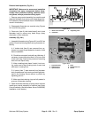
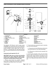
Removal and Inspection (Fig. 26.1)
IMPORTANT: Make sure to remove and neutralize
chemicals from spray components before disas-
sembly. Wear protective clothing, chemical resist-
ant gloves, and eye protection during repair.
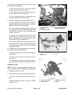
1. Remove spray control assembly from machine and
separate flowmeter from spray control (see Spray Con-
trol Assembly (Serial Numbers Above 310000000) Re-
moval in this section).
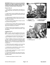
2. Disassemble flowmeter as required using Figures
26.1 and 26.3 as guides.
3. Clean rotor (item 2), both hubs (items 3 and 4) and
flowmeter body to remove any metal filings, spray
chemicals or other materials.
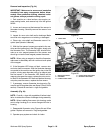
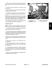
Assembly (Fig. 26.1)
1. Assemble flowmeter using Figures 26.1 and 26.3 as
guides. Check the following items during flowmeter as-
sembly.
A. If turbine stud (item 6) was removed from up-
stream hub, apply thread sealant to threads of stud
before installation.
B. Checkthatrotor spinsfreelywith verylittle drag.If
necessary, loosen the turbine stud 1/16of a turnand
check rotor drag. Continue the process of loosening
stud until rotor spins freely.
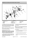
C. When installing hubs (items 3 and 4) into hous-
ing, make sure to align locating notch on each hub
with boss in housing bore.
D. If sensor (item 7) was removed from flowmeter
body, thread sensorinto housing sothat it lightlybot-
toms in the housing. Secure sensor in position by
tightening jam nut.
E. Make sure that retaining rings are fully seated in
grooves of flowmeter housing.
2. Attachflowmeter assemblyto spraycontrol andthen
install spray control assembly to machine (see Spray
Control Assembly (Serial Numbers Above 310000000)
Installation in this section).
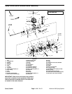
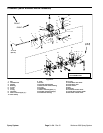
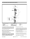
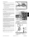
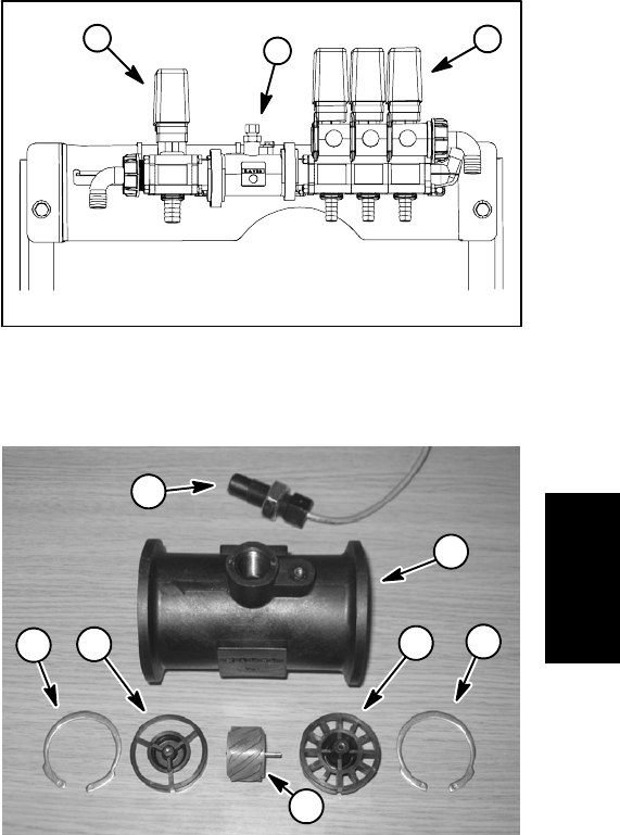
1. Boom valve manifold
2. Flowmeter
3. Regulating valve
Figure 26.2
2
1
3
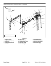
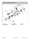
1. Flowmeter body
2. Retaining ring
3. Upstream hub
4. Rotor
5. Downstream hub
6. Sensor
Figure 26.3
1
3
2
2
5
6
4
Spray
System