Workman 200Ultra Sonic Boom System (Rev. C) Page 3.2 -- 22
Verify Diagnostic Display Output Functions
The Diagnostic Display also has the ability to detect
which output boom actuators or lights (sonic boom or
diagnostic) are energized by the Toro electroniccontrol-
ler (TEC). This isa quick way to determine which electri-
cal component is malfunctioning.
NOTE: Anopenoutput(e.g.an unpluggedconnectoror
a broken wire) cannot be detected with the Diagnostic
Display.
1. Parkmachineon alevelsurface,stop theengineand
engage the parking brake.
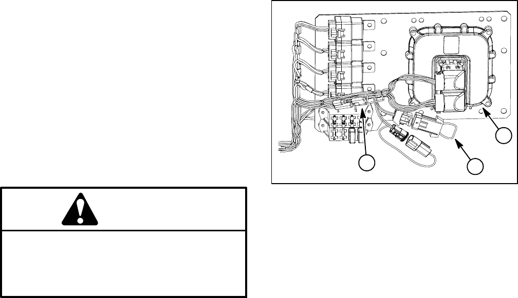
2. Locate Ultra Sonic Boom wire harness communica-
tion port and loopback connector (6 pin connector) loc-
ated near the TEC controller on the mounting plate
under the dash panel (Fig. 12). Carefully unplug loop-
back connector from harness connector.
3. Connect the Diagnostic Displayconnector tothe har-
ness communication port connector. Make sure correct
overlay decal is positioned on the Diagnostic Display
(see Special Tools in this chapter).
4. TurntheignitionswitchtotheONposition.
NOTE: The red text on the Diagnostic Display overlay
decal refers to input switches and the green text refers
to TEC outputs.
5. Make sure that the “OUTPUTS DISPLAYED” LED,
on lowerr ight column ofthe DiagnosticDisplay, isillumi-
nated. If “INPUTS DISPLAYED” LED is illuminated,
press the toggle button on the Diagnostic Display to
change the LED to “OUTPUTS DISPLAYED”.
NOTE: It may be necessary to toggle between “IN-
PUTS DISPLAYED” and “OUTPUTS DISPLAYED” sev-
eral times to perform the following step. To change from
inputsto outputs, press togglebutton once.This may be
done as often as required. Do not press and hold
toggle button.
CAUTION
WhentestingTEC inputswiththeDiagnosticDis-
play, boom actuators may be energized causing
the spray booms to move. Be cautious of poten-
tial sprayer component movement while verify-
ing inputs with the Diagnostic Display.
6. Attempt to operate the desired function of the ma-
chine. The appropriate output LED’s should illuminate
on the Diagnostic Display to indicate that the TEC is
turning on that function (see Outputs and LED Opera-
tion chart on next page). The outputs can be checked
with theignitionswitch in the ONpositionand the engine
not running.
A. Ifthe correct outputLED’sdo notilluminate,verify
that the required input switches are in the necessary
positions to allow that function to occur.
B. If the output LED’s are on as specified, but the
booms do not function properly, suspect a failed
electrical component, an open in the tested circuit or
a non-electrical problem (e.g. binding of the boom
hinge). Repair as necessary.
C. If each input switch is in the correct position and
functioning correctly, but the o utput LED’s are not
correctly illuminated, this may indicate a TEC prob-
lem. If this occurs, contact your Toro Distributor for
assistance.
7. After output functions testing is complete, discon-
nect the Diagnostic Display connector from the harness
connector and plug loopback connector into wire har -
ness.
Figure 12
1. TEC controller location
2. Loopback connector
3. Diagnostic tether cap
1
2
3


