


Rev. B
Workman 200 Spray SystemPage 3 -- 2 8Spray System
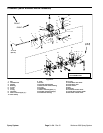
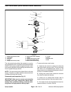
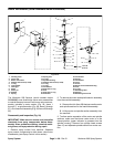
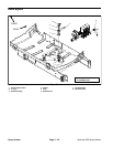
Boom Valve Motor (Serial Numbers Below 290999999)
1. Housing cover
2. Cover seal
3. Boom valve motor
4. Phillips head screw (5 used)
5. O--ring
6. Lock washer
7. Hand grip
8. Roller
9. Roller pin
10. Spindle
11. Spring
12. Spring seat
13. O--ring
14. Spindle housing
15. Phillips head screw (4 used)
16. O--ring
17. O--ring
18. Flat washer
19. Seat outer o--ring
20. Seat
21. Seat inner o--ring
22. Seat base
23. Flat washer
24. Spring
25. Flat washer
26. Cone
27. Screw
28. Boom valve manifold housing
29. Fork
30. O--ring
31. Balancing valve
32. Roll pin
33. Balancing valve knob
Figure 29
9
10
11
12
13
14
15
16
1
3
2
4
5
6
7
8
4
17
18
19
23
20
21
22
32
31
25
24
26
30
28
29
27
33
70 in--lb
(8 N--m)
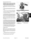
The Workman 200 Sprayer (serial numbers below
290999999) uses three boom valve motor assemblies
to control the spray booms. Each boom valve motor as-
sembly includes a motor section (Fig. 29, Items 1
through 7), a spindle s ection (Fig. 29, Items 8 through
27), anda manifold assembly(Fig. 29,Items 28through
33).
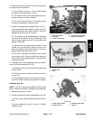
Disassembly and Inspection (Fig. 29)
IMPORTANT: Make sure to remove and neutralize
chemicals from spray components before disas-
sembly. Wear protective clothing, chemical resist-
ant gloves, and eye protection during repair.
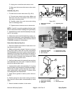
1. Remove spray control from machine. Separate
spray control c omponents to allow boom valve motor
disassembly (see Spray Control in this section).
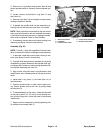
2. To remove the motor and spindle section assembly
from the manifold assembly:
A. Remove thefork (item29) that secures the motor
and spindle sections to the manifold assembly.
B. Lift the motor and spindle section assembly from
the manifold.
3. To allow easier separation of the motor and spindle
sections, make sure that boom valve motor is in the
closed position (green indicator is recessed into the
spindle housing). Remove four phillips head screws
(item 15) and separate spindle section from motor sec-
tion.