


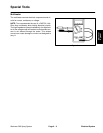
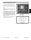
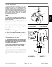

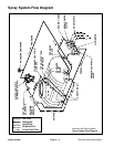
Boom Control and Monitor Power Switches
The three boom control (on/off) and monitor power
switches are located on the spray control enclosure
faceplate (Fig. 8).
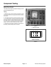
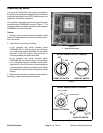
Testing
1. Remove spray control enclosure faceplate, locate
boom control switch and unplug wire harness connector
from switch.
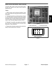
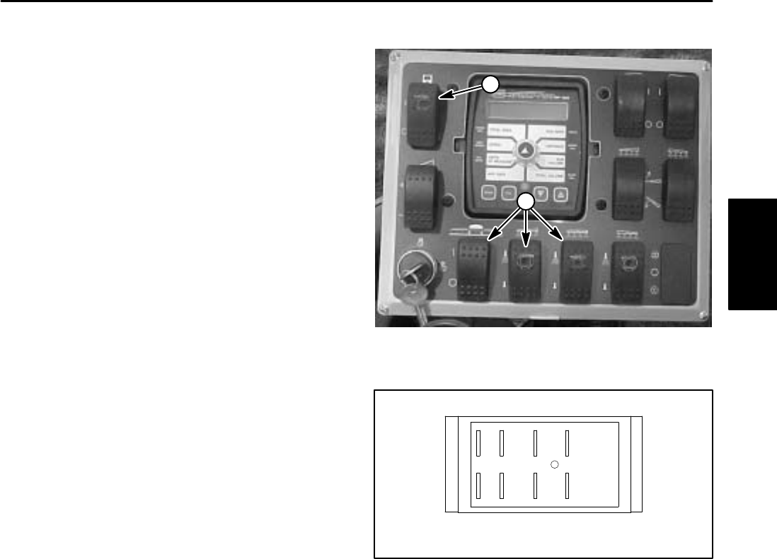
2. The switch terminals are marked as shown in Figure
9. In the ON position, continuity should exist between
terminals 2 and 3 and also between terminals 5 and 6.
In the OFF position, continuity should exist between ter
-
minals 1 and 2 and also between terminals 4 and 5.
3. Terminals 7 (–) and 8 (+) are used for the indicator
light in the switch. The light should be illuminated when
Figure 8
the switch is in the ON position.
2
1
1. Boom control switch 2. Monitor power switch
4. Reconnect the harness connector to the switch after
testing. Install console panel to machine.
7 4 5 6
8 1 2 3
BACK OF SWITCH
Figure 9
Electrical
System
Workman 200 Spray System
Page 2 – 7
Electrical System